Gnome
-
Posts
703 -
Joined
-
Last visited
-
Days Won
21
Content Type
Profiles
Forums
Gallery
Blogs
Events
Store
Downloads
Everything posted by Gnome
-
Why would you want to increase your inductance? It is effectively a huge resistor in series with your circuit. Ideally you'd want nearly "no inductance" (obv. not no, but much lower), like the grid, basically supply "infinite" current at the drop of a hat. Partially wound window, do tell, I'm not following (or perhaps not familiar with) that at all.
-
I did Google this before responding. I've not used IGBTs before but, for example 2N2222A I find painful to drive with micros because it is current driven not voltage driven. So I've opted for voltage driven when required (obv. 2N2222A is great for really low current. Darlington pair is not really my favorite, so I avoid that tbh). I assumed that for IGBTs you'd ideally still not want a current amplifier because it is undesirable to some extent to drive, no? Or are you saying it is essentially a current amplifier? (OFC there is no ideal world, logic level FETs are super expensive so I avoid those too unless I REALLY need it, linear region is a bitch on the cheaper FETs) EDIT: OFC for such a big circuit as a inverter putting drivers in for current amplifiers or even drivers that operate at higher voltage for the voltage driven gates almost certainly becomes a must. But I'm genuinely interested in the IGBT from the perspective of, how they are driven.

-
Still a MOSFET I sort of see the type of FET as being an implementation detail. They'll use whatever has the lowest on resistance and lowest switching losses with adequate current and voltage ratings. I've actually wound a few transformers now and I'd say I'm somewhat versed in transformer theory (though I always feel like I could learn more about magnetics). But the theory isn't so much important as the fact that they are wasting quite a lot of heat on these low frequency designs in the transformers. (I typed up a lot about how they are almost certainly driving the core to saturation due to its size, but I don't think it matters too much, the outcome matters) Even if they were to really up the transformer size, I'm still not convinced by the design because your inductance must be mega. Any transient you need to respond to in your circuit is bogged down by this enormous inductance. I'm somewhat curious how a LF design like Victron responds to sudden demand changes (ie. troubling electronics like TRIACs) compared to a high quality HF design (maybe even compared to their own HF design). Going through the various parts of the HF design, I can also think of reasons why it is likely easier to optimise there and get higher efficiency whereas LF design is somewhat fixed on what it can do.
-
"Low Frequency" is an older design that first uses MOSFETs to create an AC signal then drives it through a transformer to up the voltage. "High Frequency" first boosts the voltage the voltage to > ~400v RMS AC (very high frequency AC), rectifies it (usually with MOSFETs for higher efficiency than a diodes) to 400v(ish) DC, then smoothes it (using capacitors) then uses MOFSETs again to create an AC signal (the same as the low frequency design but at much, much higher voltage so much lower current, so fewer MOSFETs required so higher efficiency) If ever "low frequency" had an advantage that has long since disappeared. Its most significant advantage is simplicity of design (so easier at the design phase). The higher frequency designs have higher efficiency, lower inductance (and can thus respond faster to transients), lower weight (50/60hz transformer need to be huge). Another big factor against low frequency is your design phase is cheaper but your manufacturing costs will be higher because it is dominated by the HUGE cost of that transformer. And because the transformer is so important, it plays a huge role in your efficiency. For example, if you look at a Voltronic 5kVA inverter's transformer, it is actually pretty small for the 5kVA rating. I know this because I bought a toroidal transformer for lab purposes and the cost of a 5kVA toroidal transformer is so high that I considered actually buying a Victron inverter JUST for the transformer. So they are sacrificing some efficiency to save cost and weight during manufacturing. The high frequency inverter has a transformer in its boost converter stage but it is relatively tiny in comparison, so they don't need to cheap out on the transformer. In theory and practice high frequency designs have lower impedance and lower losses. In the early days before electronics were so good as now, maybe. But these days there is no way a company can compete with the most expensive high frequency designs. Unless your design criteria is simplicity, then, yeah sure.
-

Are electrical Joins allowed in the roof?
Gnome replied to Zapnologics's topic in General Discussion
There are a few youtube videos where guys compare connectors. Overall the winner in terms of lowest resistance but still hardy were wire nuts. Wago connectors have quite high resistance comparatively. Chocolate blocks can crush the wire. So I've switched to using the wire nuts although I didn't use to think much about them. Above was just based on making a connection and then running current through the connection to see how much current is wasted as heat and then pulling on the connectors to see how they perform in terms of holding the cable.
-
Are electrical Joins allowed in the roof?
Gnome replied to Zapnologics's topic in General Discussion
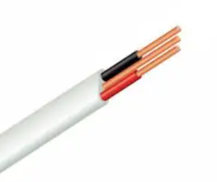
Surfix vs T&E. Surfix has a metal shield but not to be confused with armored cable or even shielded/screened cable for that matter (links to pics for each type on the word) As you can see in the regulations posted earlier in the thread, you can, in fact, run wiring in your ceiling without it being in a conduit assuming a bunch of rules are complied with. We can agree the installation picture does not comply, but the latest regulations are pretty clear that roof spaces don't necessitate double insulated wire. Whether you should install general purpose wire, instead of double insulated, when you are installing, is another debate entirely (and IMO a resounding hell no). But ofc there are "electricians" that will do the most YOLO job they can so they can spend as little time on a job as possible.
-
I'm wondering if this chemistry is not working out so well for them. The failure rate does seem very high. Perhaps they'll move to LiFePO₄ like other battery makers soon. I can't imagine this is doing much good for their profit margins. (not to mention reputation in terms of reliability)
-
The amount of fans this thing has doesn't inspire confidence. Must have some serious thermals. Why use this thing when there are so many reputable brands available that a LOT of people use? Its not even cheap... 15 amp charger. Ouch
-
There is your problem. The inverter is designed to protect electronics and 52.5Hz is very significantly out of spec
-
Honestly 10mm T&E is not something I think a lot of people use. You'll definitely have more luck calling a bunch of electrical suppliers. Copper is at an all time high, so expect to pay a lot of money for it. (online looks like R7k for 100m)
-
Two days in. Washed dishes today so not surprised by the higher usage. Also when I took a shower, water was hot, I don't even turn it to full hot on faucet Temperature inside my geyser cupboard
-
Well you can have too much if you have limited funds I also sort of got the impression OP is just using this for backup purposes, not solar (which is the same as my case)
-
Where do they give the exact experiment. Then I can contrast. But again, I'm running it again, so let's see what happens? I reset it, I have an accurate timestamp now and I can contrast after 30 days.
-
Yeah Sundays.
-
Resistive for me. But the 50w figure is total nonsense. It is a made up number that is totally irrelevant except to compare two products to each other. You need a delta T to calculate heat loss. They setup an experiment with two geysers and then the one lost 50w, the other 100w. But that is as relevant to your geyser as your car's speed is to a random car driving in a highway somewhere in Europe.
-
If you measure it on the same day, yes it'll be great at getting to a temperature and generally keeping it there. But in absolute terms it is garbage at keeping a set temperature. It has drift over time. Drift in a single day will not be significant so obviously looking at a single day is a bit like eye balling a measurement using your fingers, then calling it good. When it says 60℃ on the dial it doesn't actually mean 60℃ because they are mass manufacturing these things. There is no way they are trimming the contacts on every single one to bring it exactly into a tight tolerance. They use large bi-metal contacts (IIRC). Your drift and calibration on those is likely something like 10-15℃ degrees drift is acceptable within the product range. Whereas something like a PT100 is 100 parts per million. One device is laser trimmed, the other one is manufactured to within an "acceptable" tolerance with minimal testing. TL;DR: I don't trust the setting on a geyser thermostat. If I put at PT100 or PTC in there I'd have more confidence. But at "60℃" on the thermostat it is whatever. Probably somewhere between 55-75℃. Water if f#ck hot when it comes out and I turn off the Astute, so my guess is closer to 70℃.
-
Also good video demonstrating what I posted above
-
Lithium batteries are pretty close to behaving like an ideal battery. They'll take charge until they reach a given state of charge at a given voltage and then it will simply stop taking current. If you have a bench power supply you can easily see this by setting your lab power supply to say 2.4v. Once you reach 2.4v the lab supply will be in the mA range (self discharge). So float just means charging them to a voltage at which you have a good compromise over life expectancy and the amount of energy you are storing. Higher voltage = lower life. But if you remove the voltage from the battery completely it'll self discharge over time. If you cycle your battery often that isn't a problem. But if only use it say once a year, it'll lose a fair amount of capacity by the time you need it. Of course if you don't "float" the battery it'll last longer because you aren't keeping it at a higher voltage and thus it'll age slower. But you can't "overcharge" a Lithium battery by keeping it at a certain voltage. (assuming that voltage is below 3.65v per cell). It simply stops accepting current, the end. Lead acid terminology confuses people because they don't behave anything like an ideal battery. You need a "bulk" stage with Lead Acid to get the battery to 100% SoC (Lead Acid must be kept at 100% or its life is reduced). The reason the bulk stage has higher voltage is to overcome the significant resistance of a lead acid battery and it also has a serious inefficiency problem (This is linked to Puekart's law). But if you keep the lead acid at a higher voltage, due to its inefficiency it'll start boiling the electrolyte away. So you drop the voltage down to a point where it will prevent the battery from discharging but not boil the electrolyte. Notice that with a Lead Acid, unlike Lithium, at no point will the current stop and drop to nearly 0. It'll just keep wasting energy as heat (due to inefficiency). So in both chemistries you increase the voltage in a "bulk" stage to equalise and get them "100%". But the reasons for dropping down the voltage is very different. You would kill a Lead Acid very quickly if you kept it at "bulk" voltage. But on your Lithium cell you could run that way for years. You don't *need* to but it is a good idea if you want to get them all to a similar state of charge. You also don't need to lower the voltage if you don't want to. The charge current will drop to very nearly 0. The only reason you want to drop the voltage slightly is, higher voltage = shorter life. So once you drop the voltage the battery will self discharge a bit so that each cell is roughly at the same state of charge.
-
I assume these are the settings being set on the Axpert? So 14.25v bulk (per battery) and 13.8v float (per battery). Your float voltage is a bit higher than it was for my AGMs. They were specified at a maximum float of 13.6v and my bulk on my AGMs were 14.6v if I recall. That doesn't mean your values are wrong, but I assume you got these values from the manufacturer (of the battery) based on your temperature range? (lower temps = higher voltages) I've had dead cells before by apply too high a voltage to a battery. This is especially a problem if the cells weren't matched in terms of charge. Like I had batteries that weren't completely matched and one of the batteries would charge up more rapidly and then because they are in series it would hit a 15+v very quickly and it killed one of the cells. Does your "BMS/Balancer" provide you with per battery voltages? (And those look ok when you look at the data logs?) EDIT: I think I should also just point out, that battery is dead. You'll need to replace them... Again. So this exercise is more about figuring out what is wrong than trying to fix it. That ship has sailed, sadly
-
Lead Acid have wider operating conditions (temperature) than Lithium. They are also significantly safer. The automotive temperature range and safety are enormously important factors for vehicles. For internal combustion engines (ICE), Lithium doesn't make sense. There just isn't enough positives to outweigh the wide operating band and significant safety margin you get with lead acid. Naturally there will be people who have run Lithium in their ICE engines that will lecture me about how their experience was good, no problems, etc. But the science is pretty solid on this. For a large company making cars, it doesn't make sense to switch away from something that is incredible safe and already works 5+ years before replacement, is cheap and reliable to something that is a serious fire hazard, requires extensive protection (ie. complexity) just to *maybe* get a few extra years. It is a huge engineering effort to go a step backward. For electric cars the considerations are totally different and they can invest the cost of keeping the battery in its perfect operating conditions and safety systems in exchange for the significant increase in energy density and weight.
-
Not really, the battery will tell you what its maximum current is. But for 100Ah "AGM" it will almost certainly be more than 600w continuous. But there are multiple factors with lead acid batteries Your depth of drain determines the number of cycles you will get. For these cheap batteries any depth of drain > 50% will kill them very quickly The amount of usable power you get from your battery drops if you drain more current. So in other words, by draining 600w continuous, you may end up draining it more than you think. That all said, sounds like you are getting a dead cell, what does your wiring look like? (pic). What thickness is the various wires? How did you crimp them? What is your charge voltage? What voltage do your cells hit during discharge?
-
Hey, ok I think I misunderstood
-
Haha guys, I feel like I nerd sniped everyone here. I'm perfectly willing to accept I have a measurement error My ambient atm is around 30 degrees (in my flat, not 100% sure about cupboard, will check). I don't turn on the geyser based on temperature at all (I mean there is a max obv, around 60℃ but these thermostats aren't exactly accurate). I only turn it on for 30 minutes twice a day.
-
Axpert king + Pylontech not showing stack info on screen.
Gnome replied to Mauritius B's topic in Inverters
All the dip switches are set correctly? I'm no expert but I assume they use some kind of bus where each dip switch indicates the unique id for the device so they don't collide when they need to communicate. With one device possible designated the master and coordinating the communication. If that is def. correct I would say my faith in Axpert isn't very high, so if your battery is set to PYL in the configuration, then maybe it is "working the way it should". (aka half assed like the rest of the Axpert software; and I say this owning an Axpert King) -
Inverter is turned off and overloads? How would that happen? You mean if bypass is enabled and it is still physically powered (ie. the relay is switched to allow power from utility through?) Keep in mind when they say overload they mean the inverter (ie. 10kVA; so ~ 45 amps @ 230v). If you are overloading the contacts/relay on the inverter that is far beyond what the inverter can supply and it'll simply melt the relay contacts together.