Scorp007
Members
-
Joined
-
Last visited
-
https://api.dailymaverick.co.za/channels/lk?token=eyJ1aWQiOiJ3b29ud2FsZWRAZ21haWwuY29tIiwiY2lkIjoiMjM2MSIsIm1pZCI6IjIzNjEtMzk3MDAwZmItMDlhMC00NThhLThhMGEtYTM2YjlkYTQzNTAyIiwidHMiOjE3ODM2ODU0NDksImV4cCI6MTc5MTQ2MTQ0OSwidWgiOiI2ZmVkNzBhOWU0YjRjNjM3MjZjYTUwMTliN2Q2ZjQ3M2JlODMyOTdlOWRjNWNlODg3MTMzNjI5MTJhNGQ4YzU4In0.-HFlpE3zWE01xuU6GXKmgy7Ys0EOnzl-oLJP76H9vko&s=1783685448&url=https%3A%2F%2Fevents.dailymaverick.co.za%2Fevents%2F2026%2F07%2F17%2Fjoburgs-billing-crisis-what-to-do-when-the-city-gets-it-wrong%3Futm_campaign%3DPost-2361%26utm_medium%3Demail%26utm_source%3Djoburg Above link to join the webinar 12-07-26 at 12h00.
-
-
Negative load would in most if not all cases refer to a CT that is connected the wrong way round. Arrow must point to inverter.
-
-
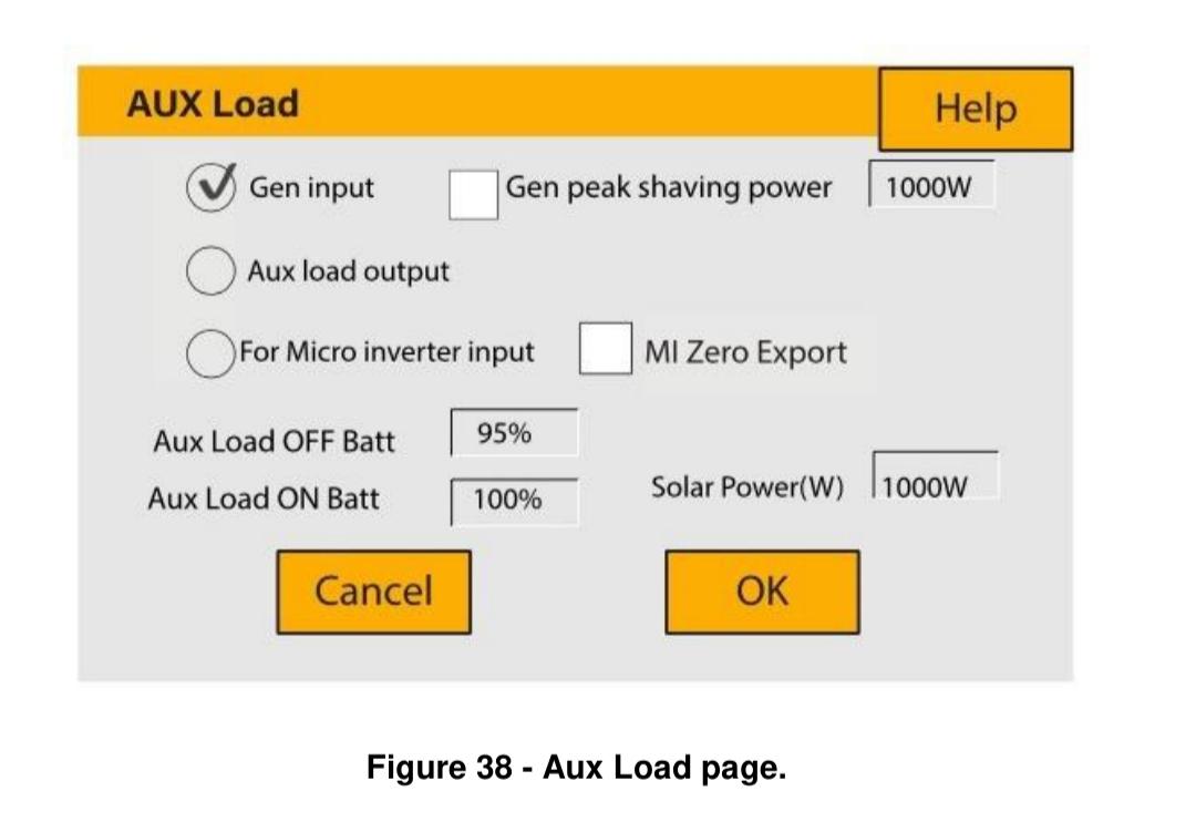
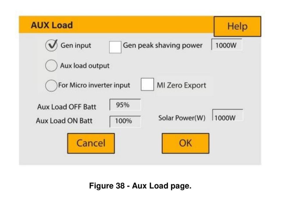
It is normal to show a low 1W if in fact the value is zero. These are the options on a Sunsynk. The Deye might just use different descriptions. On this form untick the Gen option and tick the Aux Load setting. Also supply a value like over 500W for a test. This can the be changed later. Also try with a wider setting for between which levels PV should provide a output to the Aux port. Hope this helps.
-
Can I just add we find PCBs made to order where they at times make the tracks thinner and that affects us as we measure a volt drop to simulate the current drawn by devices. This is against our spec. Anything to lower their cost. Not fun to have to change SMD resistors due to this problem. Aluminium is half the price of copper and we know how much cables are used world wide. $$$$ at stake.
-
-
-
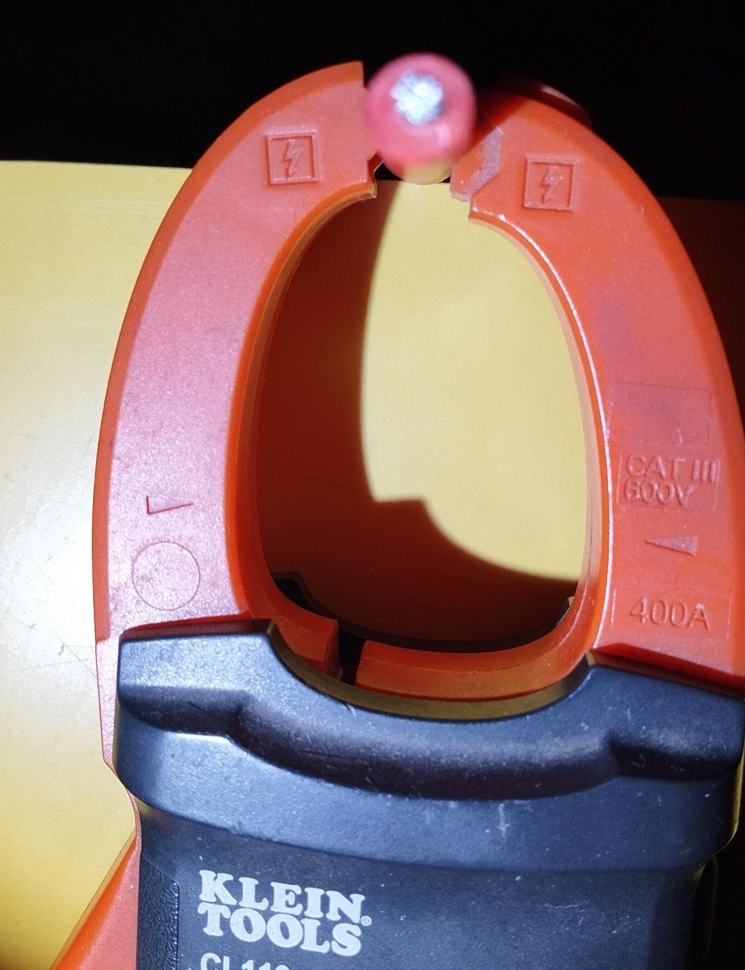
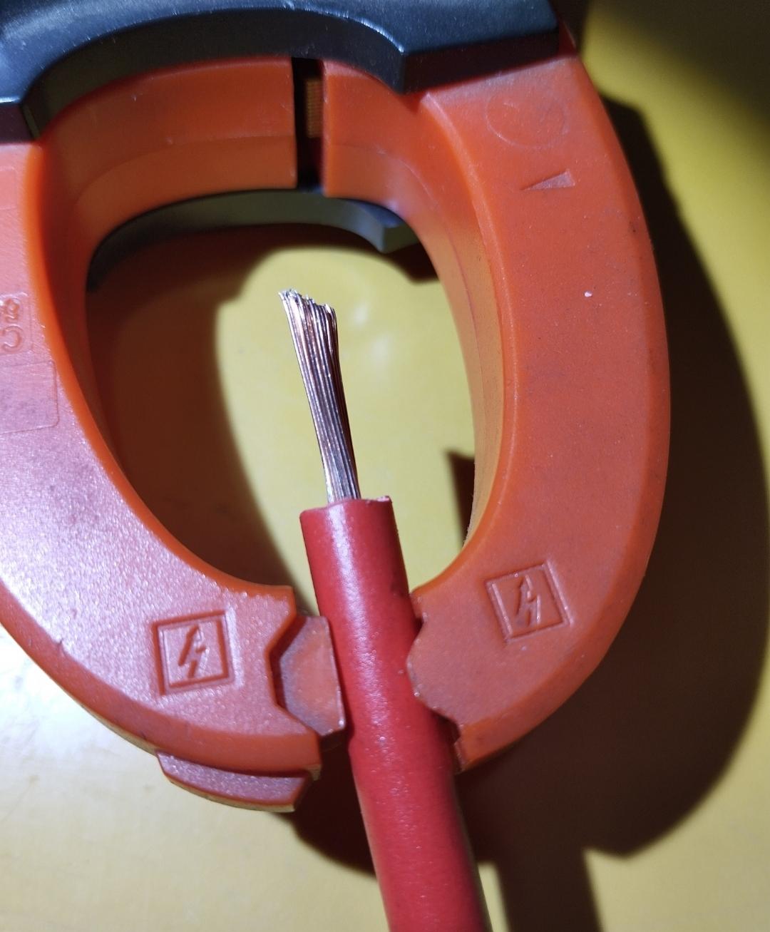
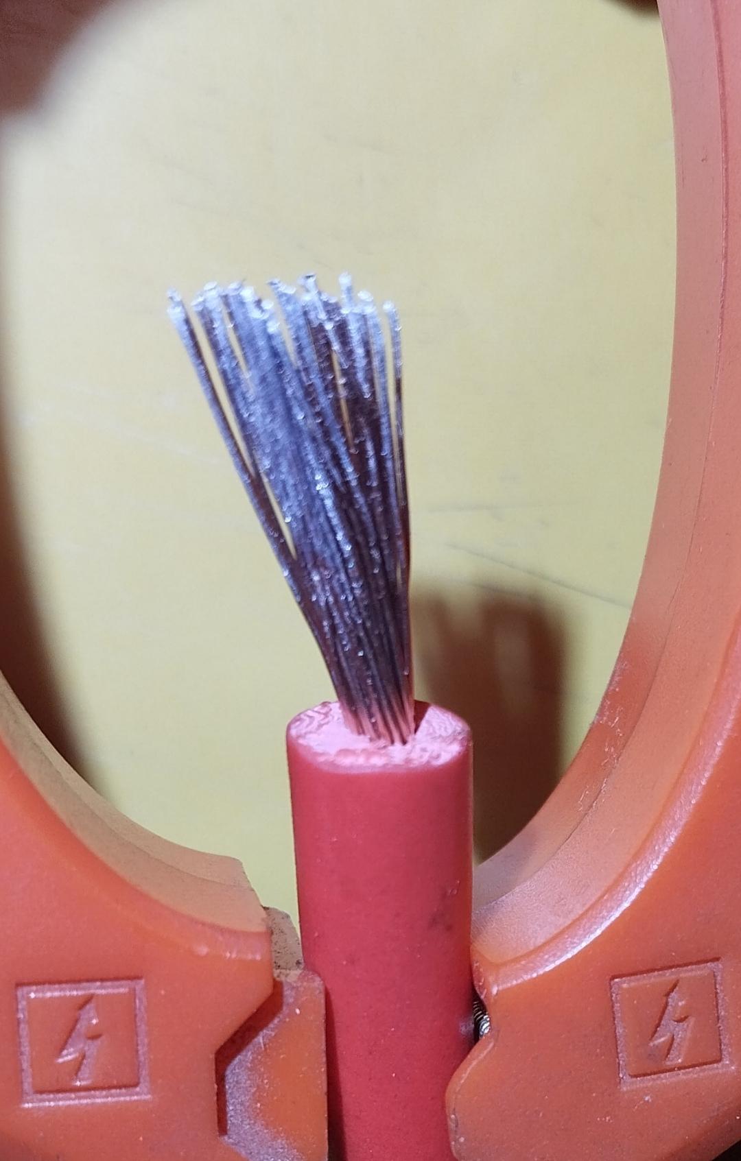
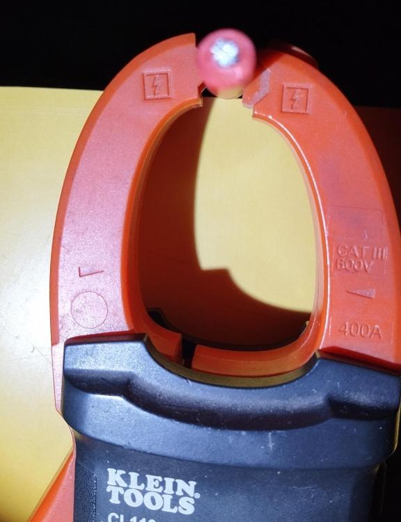
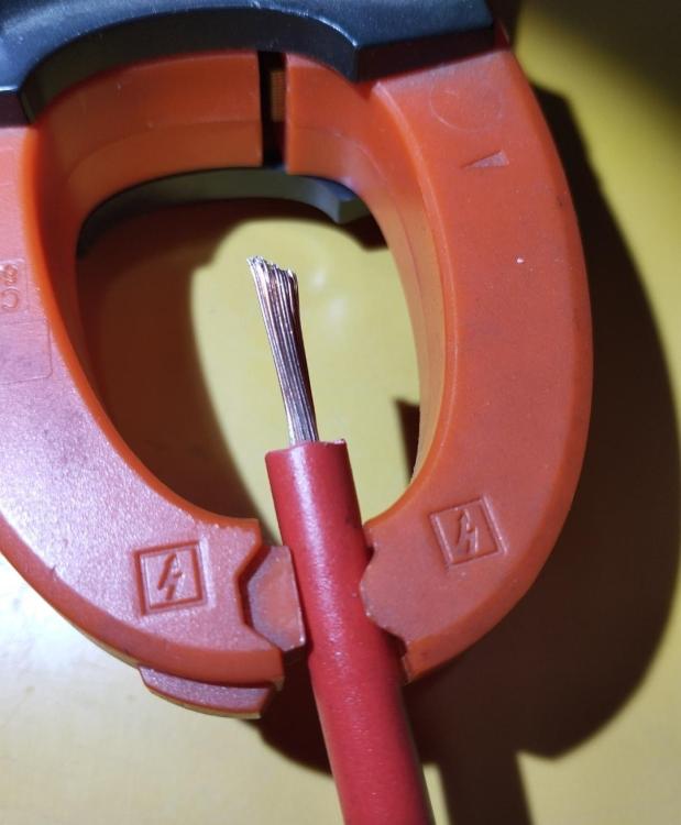
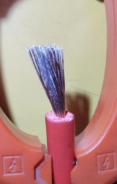
Refer to my post with the 3 pictures showing no tinned strands.
-
They say a picture is worth more than a 1000 words. This picture looks very much like the 5mm cable in the 1st post. When we strip the insulation we find no tinned copper but shining copper strands. Should we use sandpaper on the strands this is what we get. When a very good crimp with the correct cable sizes overheats suspect that it could be aluminium copper coated conducters.
-
The inside of the wire strands will not be greyish in color when you cut it if it was copper.. Those strands will have a copper color on the outside and greyish on the inside which means they are not tinned.
-
-
-
Just a bit of junk info related to the picture. The supplied cable of 5 mm² seems to be coated aluminium which has a higher resistance and a lower current rating than copper. This is something one would normally get to save cost by China manufacturers. This one can normally only see once you cut it. With car jumper leads one will also get a thick insulation of pvc to make you think it is a thick conductor.
-
-
-
-
Good to have AfriForum asking the right questions and based on what laws can a metro try and boost it's income - until all that can afford it moves to off grid R2,400 fee for people with solar panels on their roofs in...AfriForum has demanded that the Municipality of Emfuleni explain why it wants to charge residents who use rooftop solar R463 per month and a R2,400 application fee.
-
-
-
-
I am very happy that the inverter keeps my voltage level spot on during time of use activated. Been using it for 17 months. I am also off grid most of the time. I do switch the grid on via a timer after 4h00 just to always have some battery capacity. I thus use as little as 100-300wh grid during the 4h to 8h30 period. Most day even in winter no grid even in this morning period. Only when thick clouds during the day like we had the last month do I switch grid on at other times but only if needed.
-
"I do still believe the inverter's idea of SOC and the real SOC is not always aligned, meaning any inverter setting that is based on SOC is kinda a hit and miss situation." This is perhaps the case on most inverters as most will be using voltage and not measure energy via a shunt if comms are not used and voltage settings. I am wondering about the statement that the Deye might not adhere to the maximum load when in island mode. I would guess the 12kW calculates the same as the 5kW. My 5kW is set to only provide 4kW load and can confirm that it has switched of about 3 times when the setting is exceeded. My experience is not applicable to the batteries you have but see no reason why not to run in voltage mode until you got the upgrade with other batteries and going back to using comms. I am running 4 battery banks on voltage mode and they have their own BMS for the protection/balancing features. 2 are DIY. Use the inverter SOC only as a guidance and not if you want to say use 20-100% of the battery. My inverter will report over 50% most mornings but it does not concern me even if the real SOC is 35 or 65%.
-
He good news is @TaliaB has been discharge and he is busy recharging hopefully to 100% SOC on a family farm. His oxygen levels still need to recover and could take a while. Thanks for the support on behalf of our friend.
-
Even if the south facing panels provide zero PV the quoted 5.4kW PV from the 23 panels seems lowish. More data like angle, size of panels, SOC of batteries, load used and area of installation is needed to get an estimated closer answer.
-
On this point we seem to be on the same page. The only problem I see after I suggested the same is that by lowering the cut off from 24V to a low 20V does not provide the same power as it is in the area of the SOC falling off the cliff. So far a varied view on possible solutions. Adding more panels which might not be possible but @HennieL suggested a +1 going landscape above or/and below the current panels. If there is anywhere on the roof that one can fit more panels of say 167cmx90cm or smaller I will outline my suggestion. Some other suggestions like a genny (costly and noisy) or more batteries while the current PV is already lowish to fully charge is costly. May be space for a 167x90cm panel on another portion of the roof = R1300 for 330W (Vmp=36V) providing 1.6kWh/day average per year in full sun for Gauteng. Experienced installer to connect this panel to a MPPT controller that cost R900 for a smart Victron 75V/15A. This controller charges the battery directly. This controller has got a lithium profile. Thus the yield for loads and charging is greatly improved from the current system. This controller can actually even control charging on a 585W panel but will only allow about 420W charging directly to the battery. Very low loss compared to the current PWM. Yes the OP was advised correctly that panels in series where even I panel in the shade has a major affect on the whole series string. While typing this I guess even using 2 of the above controllers at R1800 fed from each of the current panels via the MPPT tech might improve charging. This is not qualified advice without having access to the data of the current system. Charging can then be 29V x 2 x 15A. The Victron 75/15 is by far the mostly used controller for lower voltage PV systems in the 12/24Vrange. @Deanos
-
 Scorp007 reacted to a post in a topic:
WANTED - Mecer Pouch cells (need two replacement pouches - Mecer Second Life EC4s2P200)
Scorp007 reacted to a post in a topic:
WANTED - Mecer Pouch cells (need two replacement pouches - Mecer Second Life EC4s2P200)
-
Thanks to @Denns and @HennieL that explained why @GreenFields and myself mentioned the combination of the PWM controller and high voltage panels make for a very inefficient charge system. I merely meant the panels are 1170W but due to the controller it will use only about 400W for charging. As per specs for the controller is given as 50A at up to say 24V is where we find the maximum that the controller can charge. This is how I see it and always open for inputs. @Denns explained very well how the PWM controller would pull the panels down to about 29V for charging the battery. The excess volts is thus lost while a MPPT would use the full volts.