Coulomb
-
Posts
7,581 -
Joined
-
Last visited
-
Days Won
178
Content Type
Profiles
Forums
Gallery
Blogs
Events
Store
Downloads
Status Replies posted by Coulomb
-
Hello Coulomb
I just want to thank you for your kindness and the trouble you took to help and assist me in sorting out my problems and getting my system to work. It is guys like you that make the world a better place to live in.
Regards MadeinRSA (Harry)
-

Thanks guys, for the very kind comments. And sorry for the late reply; the local humidity commanded my attention!
-
-
Hi, I have RCT V2 inverters some have firmware U1 52 20 and now I got an odd U1 52 32. Can you help me with any compatible firmware please? As you kindly always do.
-
Looks like I never got the time to thoroughly analyse the difference between 52.29 and 52.31. I now strongly suspect that 52.31 is the later of these two, though apparently one minor revision older than your odd inverter.
My suggestion is to update the two older inverters to 52.31, the second of the two firmwares at this post:
-
-
Keeping 8 solar panels in serie or split in 2 x 4:
Just a quick question... I have 2 x 5kw inverters with 8 x 545 solar panels, charging a 10kwh battery.
All the panels go to 1 inverter to charge the battery. Will it be better to split the panels so that each inverter gets 4 panels?
There are no shade issues or anything else. Just wonder if it will be more effective.
Panels: Vmp 41.5 and Imp 13.14
Inverters: Startup V: 120Vdc, Max input 8000W, Mppt voltage range: 100-500Vdc
Hope this make sense!!!
-
Quote
Will it be better to split the panels so that each inverter gets 4 panels?
You didn't say if you have a high PV voltage model or not. I'll assume that you have the now-more-common high PV voltage model (450-500 V max PV voltage).
For these, 4 panels in series will give you reasonable performance, except in cloudy conditions (you said no shading issues). With a Vmp of 41.5 V, I'm guessing at about 6/5 x 41.5 = 49.8 V Voc @ 25°C, say 7% more in winter or 426 V max. That should work OK for all 5 kW high PV voltage models.
There will be a slight advantage with 8 panels in series on cloudy days, but there would be a slight advantage for two MPPTs (in two inverters) with shading. Since you claim no shading, I think it would be a slight advantage to go for 8 panels in series. It's also a little less wiring, so cheaper and more convenient.
Imp should not be a factor here.
-
-
Hello Coulomb,
Can you please send me a 90.09(or other version) version for Max 8kw with minimum voltage of 180 or 200v ?
I had 46 version and the problem being stuck at 90v.
I can't find on your post the firmware to download.
Best regards,
Eugen
-
Quote
Can you please tell me at what hex address is the value for the voltage setting , in order to check what is value?
There are several places, and each firmware is different. But for all the 90.06 patches, you can find the voltage at address 3E2B2C. In the hex file, search for ":202B20" without the quotes and the two-byte word at offset C will tell you the voltage. For example, in the below:

the highlighted word is 07D0, which is the hex representation for 2000 (the voltages are represented internally in tenths of a volt, so 200.0 V is represented by the number 2000). So this is a 200 V patch.
I use the Windows program Nodepad++, which has automatic colourisation, and it helpfully bolds every second data word. You can just start at the end and work back; the last byte (here E4) is the checksum, then you have the word at address F, then E, then D, then C which is the one you want.
As a sanity check, it should always have the word 28A9 before it (the opcode for mov @AL, #), and be followed by the word 9642 (a store instruction).
Note that there will be at least two occurrences of the string ":202B20"; the second one pertains to address 3F2B2C, so you want the first one, about 40% from the start of the hex file.
-
-
Hello Coulomb,
Can you please send me a 90.09(or other version) version for Max 8kw with minimum voltage of 180 or 200v ?
I had 46 version and the problem being stuck at 90v.
I can't find on your post the firmware to download.
Best regards,
Eugen
-
Quote
Can you please send me a 90.09(or other version) version for Max 8kw with minimum voltage of 180 or 200v ?
Can you confirm that yours is an Axpert Max 1 (with the removable display) and the '2809 DSP chip? Details in this post:
If so, you could use one of the existing firmwares for that combination, e.g. the many patched versions of 90.06. There is an entire thread on patching that firmware. I believe that there are several versions with different minimum panel voltages. I'm hoping that we can eventually find a way to get one patched firmware work with all panel configurations.
-
-
Hi @Coulomb
Merry Xmas to you all down under!
Is there any reason why I get an error on one Axpert MKS 5K inverter when setting and/or changing the maximum AC charge current?
I am also having issues that this inverter does not want to charge using both utility and solar. Been struggling with this for two days now. Which settings do I need to change?
Thanks mate
Sass
-
Quote
Merry Xmas to you all down under!
Seasons greetings to you and yours also!
Quotean error on one Axpert MKS 5K inverter
It would really help to know
* What exact model of Axpert MKS 5k inverter (e.g. high PV voltage model, or 145 V max PV), and
* What was the error? A fault code? A warning code? Beep? Just won't change the setting?
QuoteI am also having issues that this inverter does not want to charge using both utility and solar.
What is setting 16, charge source priority?
-
-
Hello there
I have the xnp50-48 invt inverter how can I make sure it is axpert king or mksiii series cause I want to upgrade the firmware to a nerwer version which may let the BMS communicate with the battery TERLY brand under pylontech
-
Hello there
I have the xnp50-48 invt inverter how can I make sure it is axpert king or mksiii series cause I want to upgrade the firmware to a nerwer version which may let the BMS communicate with the battery TERLY brand under pylontech
-
> now but still get 61 on both RS485 and CAN
What cable are you using? It can't be straight through, it has to be a special one. Note that there are different cables required for early and later Pylontechs, check with the battery supplier for what pinout is required.
> will you please send the 90.06 if you have it
This is available from this forum:
https://powerforum.co.za/files/file/82-axpert-max-8kw-main-firmware-version-90067z/It is also available in patched form to reduce the severity of the "stuck at 90V" bug, but that's still a work in progress. See the long thread in the inverters forum for details.
Edit: These inverters only talk to Pylontech BMS via RS-485, not CAN bus.
-
-
Hello there
I have the xnp50-48 invt inverter how can I make sure it is axpert king or mksiii series cause I want to upgrade the firmware to a nerwer version which may let the BMS communicate with the battery TERLY brand under pylontech
-
Quote
I am trying to make my battery Pylontech work with the inverter.
Well, updating to 112.19 should enable that. The DSP doesn't have much to do with talking to the battery BMS; that's all done in the display firmware.
If 92.04 won't update, it's possibly because you have a '2809 DSP processor, in which case you'll need 90.06. Or maybe it's actually a clone and is looking for some different reflash command.
-
-
Hello there
I have the xnp50-48 invt inverter how can I make sure it is axpert king or mksiii series cause I want to upgrade the firmware to a nerwer version which may let the BMS communicate with the battery TERLY brand under pylontech
-
Quote
U1 51 00
U2 113 17
confirmedHuh. My notes say that 51.08 has been seen in an Axpert King 3kW, but that's presumably an Axpert King one (with the 145 V max SCC). But that 13.xx has been seen in a PIP-5048MGX (Axpert MKS III). Generally, those display firmwares are different to Axpert King firmwares.
So sorry, I can't tell what it is.
-
-
Hello there
I have the xnp50-48 invt inverter how can I make sure it is axpert king or mksiii series cause I want to upgrade the firmware to a nerwer version which may let the BMS communicate with the battery TERLY brand under pylontech
-
What did you try to update it to?
Your best bet would be to try to resurrect as in this post, although in this post, it wasn't a completely black screen:
https://forums.aeva.asn.au/viewtopic.php?p=94053#p94053
Attempt to update with a recent 112.xx display firmware.
-
-
Hello there
I have the xnp50-48 invt inverter how can I make sure it is axpert king or mksiii series cause I want to upgrade the firmware to a nerwer version which may let the BMS communicate with the battery TERLY brand under pylontech
-
Ok, I've never heard of that brand, so I was expecting the label to indicate it's a clone or work-alike. The sticker does look genuine. Unfortunately it's not clear whether it's an MKS III or an Axpert King II. What are the present firmware versions (U1 and U2)? Does the display look like an Axpert, with the hexagonal icons? For example:
-
-
Hello there
I have the xnp50-48 invt inverter how can I make sure it is axpert king or mksiii series cause I want to upgrade the firmware to a nerwer version which may let the BMS communicate with the battery TERLY brand under pylontech
-
Hi Coloumb
we communicated with Voltronic and they confess that there should be a firmware to allow changing of maximum charging current when BMS for LIB battery is active
do you have any clue on that.
Any contact you can share or list of firmware folders that normally voltronic used to save there own updated firmware files -
Hi Coulomb.
I see you shared Axpert MKS II 5kW Main Firmware version 71.86.7z 71.86. What is the advantage of using this opposed to my current version 71.70?
Thank you
Giel
-
Quote
What is the advantage of using this opposed to my current version 71.70?
Early Axpert King firmware seemed to have a few issues with solar charging; I'm not convinced that they are all fixed in 71.86. They may be fixed by 72.00, but it's not available for download as yet.
71.86 is obsoleted now by Axpert King main firmware version 71.97.
My brief notes in the files section mention possible improvements with battery BMS, but most of that will be due to progress with the removable display firmware. It may be that the later removable display firmwares make use of or perhaps require functionality that was introduced in 71.86.
-
-
Hey there im new ive got the sun 5k-sg01/02lp1-eu deye hybrid inverter. Im not sure how to get the most out of my system in these pics is my settings please advise me if some setting is wrong please. Im from south africa gauteng.

-
Hi. I have 2 axpert type inverters with two strings of panels (one to each inverter) and 2 LIFPO4 48v batteries (15 cell) connected together. My batteries were both at around 50% and there was more than sufficient solar available, but the axperts seem to only take in as much solar as required by the load, this varies as the load varies. In effect the batteries are basically just being "maintained" and the load serviced by the solar, but the excess solar is not used to charge the batteries. Is this the premature float bug as mentioned?
I have now manually charged the batteries from grid to 100%. My question is, why does this occur as it has not occurred in the past? Also what can I do to prevent it? The inverter does have equalisation settings, but would these be applicable to lithium batteries?
Please help!!
-
Quote
I have 2 axpert type inverters
It really helps if you say what model of Axpert. There are over a dozen, each with subtle differences.
Quoteand 2 LIFPO4 48v batteries (15 cell) connected together.
Are you using a cable direct to the battery's BMS? That makes a huge difference.
Quotebut the excess solar is not used to charge the batteries. Is this the premature float bug as mentioned?
Probably not, depending on many things. The main one is, is your battery's BMS saying "do not charge"? It's unfortunately not easy to know this. The other things are:
* What is your charge source priority setting?
* What is your output source priority?
* What are settings 12 and 13 (back to battery and back to grid)?
QuoteThe inverter does have equalisation settings, but would these be applicable to lithium batteries?
It depends. If you have your float voltage setting the same as the bulk voltage setting (this happens if you are using "the cable" and battery type = PYL, for example), then no, this doesn't matter, and the premature float bug doesn't matter.
-
-
I have Voltronic VM2 Infini Mode 3KW 48 Volt (On Grid Of Grid), want to connect them parallel but both inverters have different firmware one of them has U1 13 21,
i need firmware to make them same, kindly help me to update firmware please
-
Hi Coulomb,
I was told maybe you know what to do with my inverter.
I have a three phase installation with Growatt SPF5000es inverters. After 2 weeks, I had no longer communication BMS with the pylontech 2000C batteries and could not find the problem.
I tried to update the firmwares under win7 (I was told that it doesn't help for com issues but seemed at the time reasonable). Two updates went well. However, one inverter didn't accept the 040.06 FW, but did accept the 041.06. I did a hard reset, with no success. All leds of cards are still operating but I get "send start" for hours.
Now this inverter no longer detects solar and is no longer detected by the other inverters (error 17) but it still starts and seems operational. I also have full access to the menus.

Can it be related to the com card or ... ?
Thank you for any suggestion.
Eduard (France)
-
Quote
I have a three phase installation with Growatt SPF5000es inverters.
Alas, I don't know much about 3-phase inverters, and not much about Growatts. But they do seem to be based on Axpert designs, so there is some hope of me making sense.
QuoteTwo updates went well. However, one inverter didn't accept the 040.06 FW, but did accept the 041.06.
All I can say is, maybe, just maybe they operate like the Axperts, and you can retry the firmware send. It sounds like you already did that, but maybe you need to turn on AC-in power at just the right time, like with Axperts.
See here for all I know about restarting Axpert main firmware updates.
-
-
Hello Coloumb
What do you think causes error 53 and what will be the solution of such??
-
The difference between pins 3 and 4 should be proportional to the AC output instantaneous voltage. The top half of the two voltage dividers are on the main board, the bottom half of the dividers is on the control board.
You won't be able to measure anything there until the full bridge (DC-AC converter, inverter proper) is running.
-
-
Hello Coloumb
What do you think causes error 53 and what will be the solution of such??
-
Hello Coloumb
What do you think causes error 53 and what will be the solution of such??
-
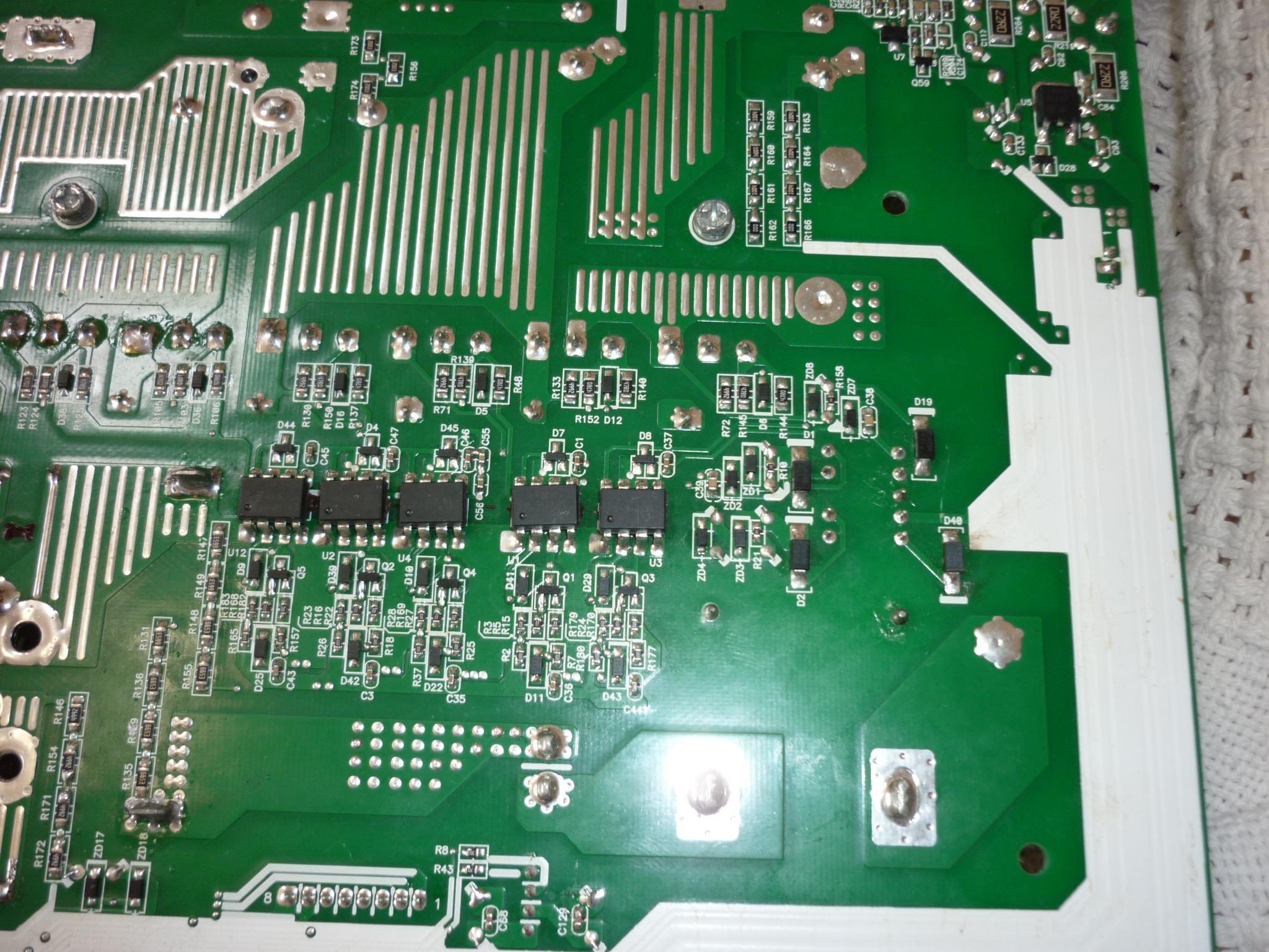
I would have thought that a person having ordinary skill in the art would know these components pretty well. But here are a couple:
As well as the labelled current sensors, the four full bridge IGBTs are at the left, the LC filter are at the extreme left and the large black box near the middle, there is a green common mode choke to the right of the filter capacitor, and two relays can be seen at the lower right.
Under the board, the IGBT gate driver components:
The 5 8-pin driver chips can be seen in the middle, with DSP-side components below, and gate-side components above them. A "transformer" (TX7 on most models) supplying isolated gate drive voltages is to the right. The resistor chains for the output voltage measurement are at the lower left.
See also the traced schematic for a 2013 main board. Also see the relevant service manuals in the files section of this forum.
-
-
Hello Coloumb
What do you think causes error 53 and what will be the solution of such??
-
It so happens that I've just started investigating the inverter soft start process.
It looks like the inverter starts with a low target voltage, and they increase the target voltage by 5 volts every so often (possibly 50 times per second). I'm unclear what the relays are doing while this happens, but I would guess they should all be off. If the inverter voltage fails to reach the nominal voltage less 5 V in a certain time, and a few other conditions, then fault code 53 results.
In other words, the inverter can't reach its intended voltage, as measured by the output voltage op-amp and associated parts.
So fault code 53 could be caused by any failure in the full bridge (e.g. the 4 IGBTs and their gate drivers), the output LC filter, or the current transformer primary is open circuit, or a fault in the output voltage measuring circuit. Some of the EMI filtering capacitors or the MOVs could also be indicated.
-
-
I know you are a pro when it comes to axpert inverter repair I have a 5kva axpert inverter that when you power the system with battery and turn it on it starts and supplies under voltage and goes of immediately and come back on it does this continually without going off until you disconnect the battery
-
"it starts and supplies under voltage"
What you you mean by "under voltage"?Are you saying that the AC output produces less than 230 VAC?
Or doesn't it even get that far? (It sounds that way).
How long is the display on, after the "lamp test" that turns on all LCD segments?
Do the various power supplies (+12V, -12V, +5V) come on with appropriate voltages?
If you remove the control board, do the power supplies come up and stay up?
-
-
i have inverex aroxe vmiii i required reflash tool exe and firmware