frankthetank
Members
-
Joined
-
Last visited
-
@Ar135 1. I can only assume your Deye is supplying the RS485 board which has a working voltage of 5v. I have tested with a meter and my inverter supplies just under 4v from the RS485 port and when connected to the A and B on the board it drops down to around 1.2v hence the dim flashing on the RS485 module. 2. When I plug the red in as well either 5v or 3.3v it really lights up and stays solid. 3. There seems to be no consistency with a setup as for some people it works with only 2 cables and some works with 4, some without power and some with. I have read some people removed the GND and it started working!! I end up spending hours a day trying different combinations of pinouts and cabling and always the same results. The only thing that changes is the colour and thread count of my hair. Maybe someone can post an example of what the working logs in ESPHome look like? Quick Spec Onboard MAX485 chip provides a low power consumption for RS-485 communication. Onboard 5.08 (mm) pitch 2P terminals, to facilitate the RS-485 communication wiring. All of the pins have been led by the MCU control operations Working voltage: 5V Board size: 44 x14mm
-
Hi @Ar135 Just to confirm are you running any power from the ESP32 to the RS485 or only the GND? I have red and black going to the RS485. I have tried with the 5v and the 3.3v which lights up the LED on the RS485 and then also tried no power only the GND which then the LED on the RS485 flashes dimly.
-
Hi @ScOObs Thanks for the response, I'm in Durban. Yeah, I have 2 x RS485 boards one with and one without the R7. I have tried the following cabling options on both CAT 5e and CAT 6 1 O/ to B 2 O to A and visa versa 2 O and 7 B/ to A 1 O/ and 8 B to B and visa versa I have used pinouts GPIO1 and GPIO3 and swapped and also GPIO17 and GPIO16 and swapped. Flow control of GPIO4 I have put a volt meter on the RJ45 cables and getting around 3-4v when connected to the RS485 port on the inverter. It then drops down to around 1.2v once wired into the RS485 - TTL board. The 8kw Sunsynk has an RS485 port and I think only the 5Kw might have shared a port with the CANBUS buy I could be wrong. I also tried 2 different ESP32 boards. I agree that there is a communication issue from the inverter just cannot for the life of me figure out why. My other option is to run a longer network cable directly into my HA box which is running bare metal on a spare laptop. RJ45 Looks like this

-
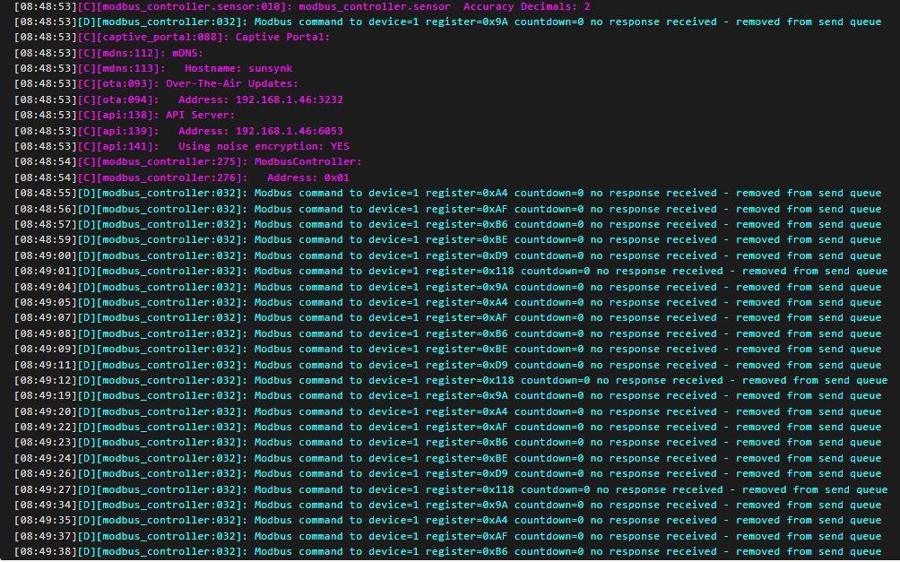
Hi All I have been at this for weeks and have never been this frustrated with a project in my life. I just don't seem to be getting a response from my inverter to the ESP32 Dev board in ESPHome. I have tried multiple ESP boards with multiple RS485 TTL boards and RJ45 cables and cable pinouts. Please someone out there save my marriage!! I have followed "Solar Integration" Channel with Slipx06 yaml files and pinned out accordingly with all the troubleshooting steps. These are the logs and yaml config. Modbus on the inverter is set to 1 substitutions: settings_skipped_updates: "30" devicename: sunsynk device_description: "Sunsynk RS485 Logger" friendly_name: "SunSynk" esphome: name: $devicename comment: '${device_description}' esp32: board: esp32dev framework: type: arduino # Enable logging logger: baud_rate: 0 level: DEBUG # Enable Home Assistant API api: encryption: key: !secret api_key ota: wifi: ssid: !secret wifi_ssid password: !secret wifi_password # Optional manual IP manual_ip: static_ip: 192.168.1.46 gateway: 192.168.1.1 subnet: 255.255.255.0 # Enable fallback hotspot (captive portal) in case wifi connection fails ap: ssid: "Esphome-Web-9Ce5D0" password: "" fast_connect: true power_save_mode: none captive_portal: time: - platform: homeassistant id: homeassistant_time uart: id: mod_bus tx_pin: 17 rx_pin: 16 baud_rate: 9600 stop_bits: 1 parity: EVEN data_bits: 8 modbus: id: sunsynk_modbus flow_control_pin: 4 #send_wait_time: 500ms modbus_controller: - id: sunsynk address: 1 modbus_id: sunsynk_modbus setup_priority: -10 update_interval: "15s" command_throttle: "50ms"