


MarinusG
Members
-
Joined
-
Last visited
Everything posted by MarinusG
-
No disagreement here, other than to clarify: the parallel configuration means that the inverters are in the same mode - i.e. the non pv-connected inverter will source it's AC output energy from the battery bus (it cannot bypass mains while the PV connected inverter is using PV / battery). If there is surplus PV on the PV connected inverter, it will direct this to battery charging, subject to configured limits for the charger. All being well the non pv-connected inverter will only suffer the losses across two sets of battery cables. Alternatively we see the round-trip through the batteries (with losses). My understanding anyway...
-
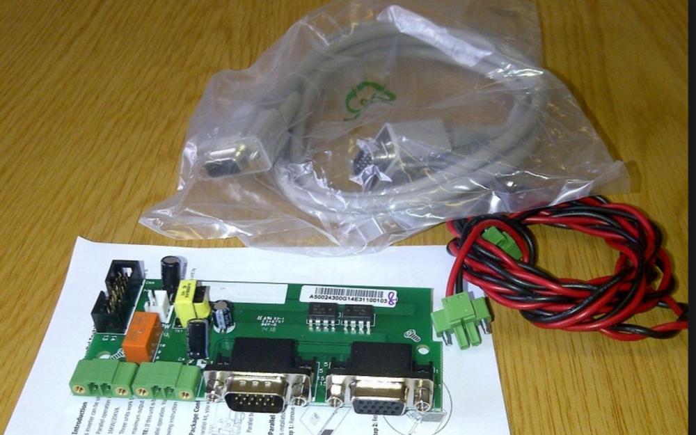
Apologies - I was teasing about the parallel cable kit . Agreed on the battery cables - using 50mm^2 throughout on my setup.
-
From the above, the statement seems to be that 9 / 12 panels on one inverter and 0 on the other will work fine and that there is no difference between this arrangement and splitting the panels evenly across the two inverters. Later there is the following statement: I think we need to be consistent to avoid confusion here. My understanding is that the inverters share the load current in a parallel configuration. I'm not sure how, in 'solar' mode, an inverter without a PV source can provide current to the load, other than drawing from the batteries. Even though this arrangement may 'work fine' there must be some efficiency loss across the DC bus and round-trip battery loss depending on the restrictions imposed by charge current limits that may exist on the PV connected inverter. It may be instructive to conduct the experiment and identify where the non-pv-connected inverter is sourcing current from (clearly not the little black and red wires between the inverters!). The comment around day time relates to charger and load source priority - i.e. charge from pv when pv is available or use grid to charge and supply load with Solar when solar is available.
-
While this seems to be OK, I would be tempted to move a string across to the second inverter. This keeps the two inverters in a consistent mode. I'm not sure exactly how the current sharing is done, but having PV on both at least lets them agree that it's day time, when it is...
-
I've included my settings for the 3 Axpert cluster that I have installed along with some of the thinking behind each option (based on my understanding). The system has been pretty solid in this configuration using AICC to monitor and control. Firmware 72 40 and 01 24 respectively Pretty happy with the charging that I'm getting: going to float just after 12:30 (BMV is triggered to 100% a bit earlier...) 01 SBU This mode is for on-grid use where you want to minimise grid usage. It will use the battery whenever solar is not available. It will only use the grid when the battery gets low. Link 02 70 This is within the limits of my battery bank - i.e. I can safely charge at a total of 210 Amps for the 3 Axperts combined. Solar can provide roughly 60 Amps maximum per Axpert (3kW). This will set the upper limit for solar charging and should we within the limits of connected batteries. 03 UPS Conservative setting for grid voltage range i.e. if grid falls below 170V or rises above 280V it will be deemed to be unavailable 04 SdS Inverters should remain on regardless of load 05 USE User defined battery settings 06 LrE Personal preference - I have protection breakers installed on all circuits supplied, so comfortable to restart in the event of overload 07 trd More worried about temperature - so disable restart for overheat 09 50 50hz for SA 11 10 Small charge current from grid if the batteries dropped below SOC specified in AICC 12 45 Lowish voltage for back to utility - this is a fail-safe in the event that AICC doesn't switch for some reason and the batteries are being drained. This is an anti-nuisance setting to avoid accidental switching in the event of high load walk-ins. 13 50 Lowish voltage for back to Solar - shouldn't need this since AICC is in control, but will avoid unnecessary use of grid if the Axperts switched. 16 CSO In the event that the batteries drop below SOC specified on AICC, use grid to trickle them up to avoid standing discharged (limited by setting 11). Useful for a 'full charge day' 18 BOF No beeping 19 KEP Stay on the selected screen 20 LOn Keep the back-light on 22 AOF No beeping 23 bYE Enable bypass in the event of overload 25 FEn Not really getting any faults, but keep them when they happen. 26 56 Specific bulk charge voltage for my bank 27 54.8 Specific float charge voltage for my bank 28 PAL Parallel mode 29 44.5 Last resort cut-off voltage in the event of no grid. 30 ONE As long as one Axpert has PV available, honour setting in register 1 31 SbE Solar balance enabled for maximum utilisation of solar energy.


