PaulNaude01
Members
-
Joined
-
Last visited
Everything posted by PaulNaude01
-
Thanks for the advice. Much appreciated.
-
Hi @Coulomb Regarding your advice below about the 48v, I am a bit confused now, also trying to interpret the Pylontech manual and how to set the charging settings correctly on my inverter. The us3000c manual (attached) only states these values: Discharge Voltage (V) 44.5 ~ 53.5 Charge Voltage (V) 52.5 ~ 53.5 Yet on the inverter, one has to set all these (with what I thought would be correct, in brackets): Shutdown battery voltage (44.5V) To grid battery voltage (45V-50V depending on reserve required) Back to battery voltage (53.5V) Battery float charge voltage (52.5V) Battery absorption charge voltage (53.5V) So if this is incorrect, how should one then interpret the manual's values to set the inverter correctly? US3000C-MANUAL.pdf
-
This must be the excuse I've been waiting for to buy a more expensive multimeter 😉
-
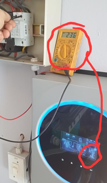
Can a cheap Volt meter get the DCV reading this wrong? Measured at the solar panel supply, into the lightning arrestors, from where it goes directly to the inverter.
-
This seems to be the easiest to implement in any case, to take the three inputs which are currently in parallel and put them in series, taking the total input Volts to a maks of 360V, which is still safely in the inverter's input range.
-
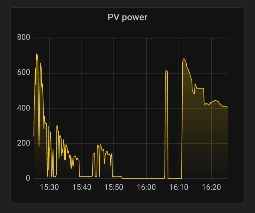
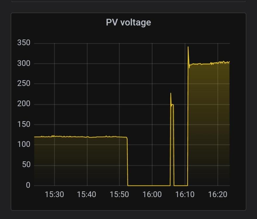
This seems to be the issue, yes. I've added more graphs showing the voltage and power from the panels. Do you think it is the current heat wave that causes more resistance and drops the voltage?
-
I'll have to check!
-
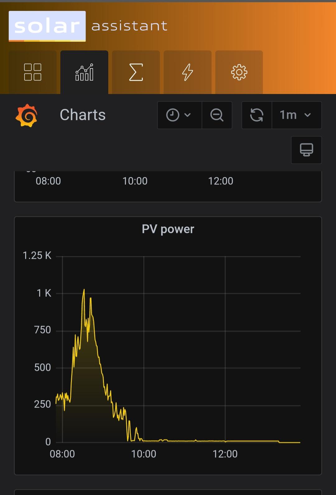
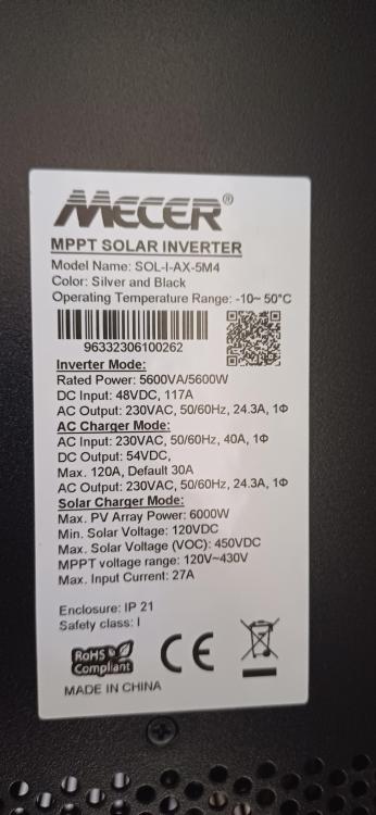
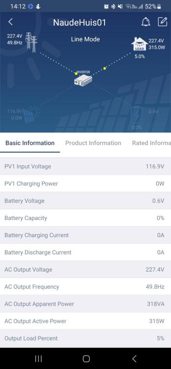
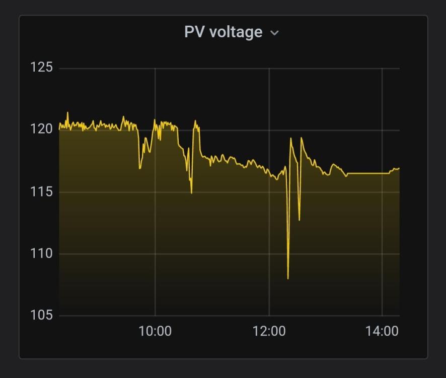
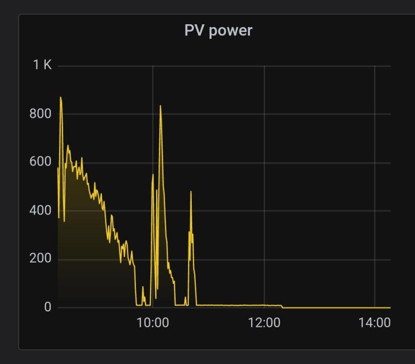
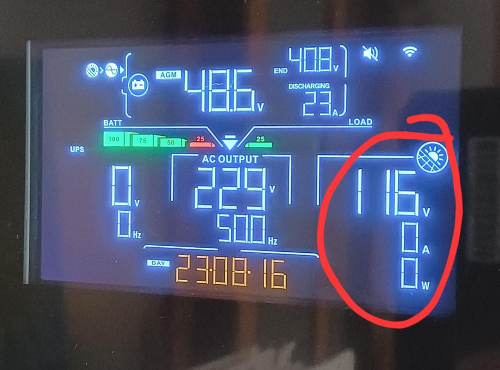
Thank you for all the replies. The panels were installed in 2018, 330watt units from ArtSolar. 3 strings of 3 panels, 9 in total, thus a total just shy of 3kW The inverter details are on the image attached, a 5.6kW unit Some of the unit status info is attached too and today's Volt and power graphs. The issue seems indeed to be that the voltage drops below the minimum of 120v.
-
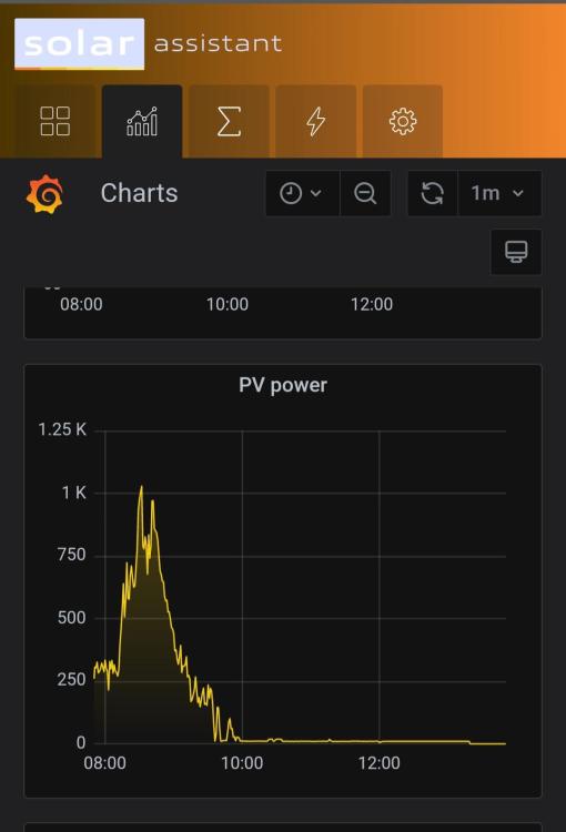
Hi [Resolved! Many thanks to the hawk eyes of this forum's members] We noticed over past few days that despite the cloudless days, the batteries didn't charge fully as in the past and both Pylontechs and the inverter is new. The panels and installation however are not. For the duration shown in the graph and display, there wasn't a cloud in the sky and no shadows from trees, but the panels deliver no to very little current despite showing a Volt supply. Early morning around 8, I decided the panels may need a clean and although not overly dusty, I cleaned them with a towel and water in any case. Shortly after add shown in the graph, the current dropped to zero and didn't pick up again despite full Sun When switching off the circuit breakers on the panel input circuit, the Volts dropped to zero and each of the circuits with 3 panels each independently showed a voltage too. I don't understand why the supply started dropping over the past week or so and how all three strings can have the same problem at the same time. [Reason and solution] The new inverter has a minimum input volt threshold of 120V and due to the extreme heat, the combined volts from the panels dropped just below this threshold every day around 10am as shown in the graphs. With the 3 panel sets now in parallel, the total input Volts is now 3 times higher and still within the allowed range of the inverter. Everything is running smoothly now. New graphs added.
-
Ha ha, I thought of that too!
-
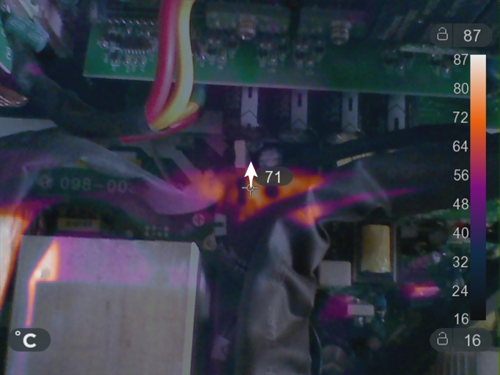
Thanks @jumper You make some very valid points. I didn't think about the location of hot components and the temp sensor. That could surely make an important difference. I have also managed to take a few thermal images (the overlay has a slight vertical offset) Apart from the coil, the other hot (visible) components are these: Regards

-
Thanks @jumper. I would like to look into the fan designs in more detail. My limited fluid flow knowledge says the mass flow before and after the fan must be the same. What I would like to investigate however is what happens further away before and after regarding the flow patterns which could make a difference in terms of the airflow patterns through the heat source area. In a closed horizontal pipe system, the air flow has to be identical on both sides otherwise mass conservation does not hold. What I do think makes a difference is gravity and with that, dust. In the pull down configuration, the heated air is less dense and wants to rise while the fan pulls it down. In the push configuration the air wants to rise and the fan is helping it on. Regarding dust, in the pull scenario the dust will happily enter the inverter and collect on anything in the way. In the push configuration, the only way dust can enter is if it goes up, against gravity and with less ability to collect inside. I wouldn't mind being proven wrong since I like to learn. Yes this was a really weird discovery. Apparently the correct terminology is that the one fan needs a pull up resistance and the other a pull down resistance. Fortunately, it was a relatively easy fix with an Arduino laying around to monitor the Inverter signal and provide the opposite to the fan. It was only a few lines of code. My inverter now runs silently (my laptop fan is now more audible!) and the inverter hasn't had a single error 51 since. In all honesty, I think the higher RPM (and by implication the CFM rating) on the new fans is far more important than the direction of air flow, but every bit should help.
-
When taking the fans out to reverse them, I discovered that the one fan did not rotate smoothly anymore so I decided to replace both of them with new fans (which also happen to have a higher RPM and flowrate). Then something very strange jumped out of the wood work. After installing the new (also 4-wire fans), the new fans ran at top speed all the time and the noise was just too loud to ignore. Despite the noise, it bothered me that although the load on the inverter changed as normal, that the fans did not ever slow down. I searched the internet for datasheets of both fans and could not find anything useful on either regarding the extra wires (speed control and speed measurement) to double check that these wires are indeed doing the same thing. Since the new fans had a higher RPM spec, I though that maybe the controller on the inverter are simply tuned to the old fans and therefor let the new fans run too fast but I could not find anything to work with. Now comes the scary bit. After searching some more, I found a site explaining the functions of the blue and yellow wires of IBM PC motherboard fans and this correlated with what I could test on the new fans: If the blue wire is free (or have a high resistance to ground), the fan runs at full speed and when it is connected to ground (or has a low resistance to ground), the fan runs at a slow (minimum) speed. I measured the resistance range and found that at 2.5kOhm or higher, the new fans runs at maximum speed. I tested this on the old fans and they didn't even run with 12 volt supplied, except for a quick jerk of blade movement when switched on. So I set of to test what the inverter supplies to the blue wire (I had my suspicions) and indeed, the blue had a voltage (of 0.35V), NOT a resistance supplied! I fitted the old fans and indeed, without the blue wire, they didn't run and with it connected, they ran at a high (possibly max) speed. So now my question: Why on earth would fans be sold without this information freely available, especially when they function totally different and void of clearly any standard? And then more importantly, what would be the easiest way to convert a voltage to a resistance, to use the new fans?

-
So I managed to borrow a thermal camera and here is a semi-overlay showing the hottest elements at the top of the inverter. Considering that the factory default fans are installed at the bottom, and blowing down, it makes sense that these components won't cool down.

-
A thermal camera might be quite interesting to use, yes. I also think it can be degradation, probably helped along with inefficient cooling.
-
Hi @Beat My inverter ran without any issue for about 4 years now and in some cases like in this post, the issues also only started many years later. I don't really want to re-design the cooling for the supplier (they should do that) but there is clearly a problem and changing the cooling fan direction can only help in my opinion. The only downside I can spot is more dust that can accumulate over time, so maybe the inverter must be installed upside down 🤣
-
Update: It's been 24 hours now without any interruption or error codes!
-
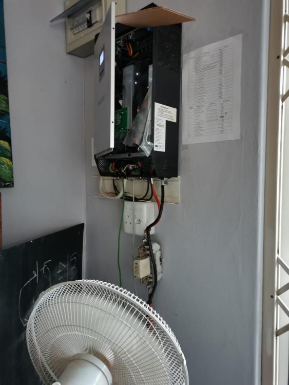
After my Axpert inverter progressed from intermitted Code error 08s to nearly constant code 51s (regardless of weather, time of day or whether or not Solar and/or grid was supplied), I started to study the many related posts on this site. I wish to thank the following contributors for their valuable contributions, in no particular order,: @charlez @Maximus777 @Coulomb @APV @Chris Knipe @jaco de jongh (not sure how to tag him correctly). What stopped me short of starting to replace mosfets and caps, were the amount of boards to remove just to get to them! I started weighing the costs of getting a new unit and developing my assembly skills when I made a discovery, quite by accident, that have allowed the unit to run today for 12 hours straight(!), through 2 load shedding sessions, intermittend cloud cover, without as much as a single beep. I can't find who mentioned something in one of the many posts about reversing the fans, which I did not pay much attention to then and also because no one really reacted on it but I remembered it when I looked at the uncovered monster before me (still mounted and connected on the wall) and me very reluctant with a set of screw drivers in hand. With only the front panel removed, I switched the unit on one more time and when the fans started, felt the wind blowing down, out of the unit, not up and in over the heatsinks. Now I have never designed or sized heatsinks or any electronics cooling systems before, but I know hot air moves up and these fans are trying(?) to sucking the air down. That just seems counter productive. I wanted to remove and turn the fans around but again, their screws are only accessible if you dissasemble many other parts first, so I sighed again. Being Easter monday and not wanting to spend more time on the inverter, I left it at that, and then this morning I had an idea: Let me test this: I openend the front panel again, openend the plastic sheet to allow air in, and placed a floor standing fan at full speed blowing at it! Wolla, the inverter still works without any error while it would have been tripping 20 times by now in the same time frame. Can it simply be that the inverters are assembled incorrectly, with their fans blowing out (down) and not in (up), to cool the heatsinks? My experimental setup (no, I don't have small children in the house anymore!): And yes, I have a list of error codes on the wall. I should have ticked all the ones I have encountered already... So, this seems like a succesfull hack and worthwhile to get those fans out and reversed.