nogers
Members
-
Joined
-
Last visited
Everything posted by nogers
-
Hi coulombe. So it's not a source either. The supply voltage of the source is smooth and stable. It should be noted that the converter is only a few months old and has been in operation for about a month. It was fully functional until I connected ground and the PV input. This caused the destruction of the Igbt and a short circuit. I believe it could destroy something on the output of the inverter and that is now destroying the new igbt again. The problem is that I can't even find any errors in the output. For example, a faulty capacitor or relay. Low switching voltage of Igbt should not destroy the inverter without load. Do you think this idea is correct?
-
Hello @BritishRacingGreen. So after a long time I finally got around to measuring. pin 5-8 4.95V and 5-7 12.28V so absolutely fine. Resistor and capacitor also fine (3.9nf and 8.25ohm). The input to the transistor was measured and on the range of 2 microseconds it looks the same as your measurement. I don't see a problem here. I don't know how I got the 2ms measurement range. Any other idea what it could be?
-
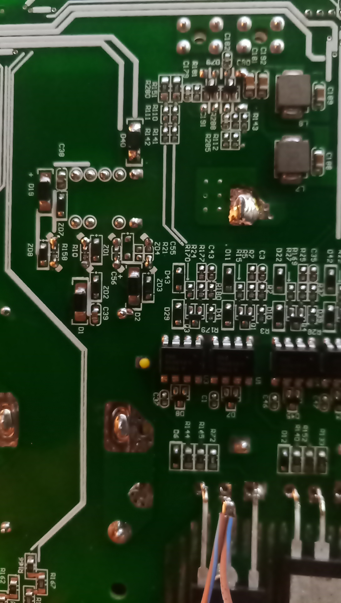
So I measured almost everything possible and did not find the error again. R215 has 149m ohm. Measured with a Grundig RLC200 four-point RLC meter. The power board has 48v written on its output and its output is about 47v. That's okay too. I also measured the excitation voltage of transistor Q36 about 10V and the input voltage of tx9. See picture. I think everything is fine.

-
hi @BritishRacingGreen. So everything absolutely agrees. As for the voltage level, it is about 25V at the input and your measurement shows 36V, that's the only difference. Maybe it's meant to be, and the problem is somewhere else entirely. Basically, I also have a borderline input voltage of 48V. and you said that the min is 40V and the max is about 60. This voltage would theoretically raise the voltage overall even on tx7.

-
Hi @BritishRacingGreen My converter is only a few months old and it doesn't look like any of the components around the igbt are damaged. It is also clear that the short PV to ground caused the destruction of the igbt. But if the transformer tx7 or tx9 should be damaged and the surrounding components are not damaged, it does not seem logical to me. I'm starting to wonder what could be causing it. Thanks.
-
Hello @BritishRacingGreen. Such a small voltage is not only on zd8, but on all zd for igbt. I also measured the load of the individual Igbt sources and measured 2mA on two and 4mA on the third. This eliminated the possibility of a short circuit, even when all igbts were switched on. Sorry for the inaccurate description. I think the overall low voltage comes from tx9 and d20 (in my plan and on my d40 board) tx9 is a +12,+5,-12V source and these spikes are all fine. Therefore, it is not clear to me why the Igbt voltage is not correct.
-
Hi. I did all the measurements again exactly as per your instructions. The only difference is the voltage level of zd8 (12.8-14.5v), in my case it is only 8.3V and on igbt 7-7.3v when all igbt transistors are switched on. The voltage without igbt switching on zd8 is 8.49V. All voltage is generated directly from the tx9 transformer. I have already measured these pulses and according to Coulomb everything is fine up to the level of positive voltage. No ripples or other deviations were detected. I used the original source for all measurements and it has an output voltage of 48.5v. My power supply is only 32v 10A.
-
I'm glad to find people on this forum so welcoming and helpful. Thanks. I also thought of measuring the consumption of sources for the igbt with an external source of approx. 20V through a 1k ohm resistor and two have 2mA at a voltage of 17.5V, and the third connected to the BUS- takes 4.3mA and 14.5V. Sources and static subscriptions seem to be fine.
-
Hello British RacingGreen. The best thing about the inverter is that it worked fine until I connected the ground and the PV input. So I know why he destroyed himself. I just don't understand why it doesn't work after replacing the faulty transistors and not finding another fault. In theory, the destruction could continue to the opticouplers or source for the igbt. Probably not anymore. It's weird for me to modify something that worked before. And despite the fact that I added the missing parts, the signal according to Coulomb is disturbing. If someone could measure the correct course of the signal on the igbt and perhaps also on other timing converters, it would help a lot in detecting the error.
-
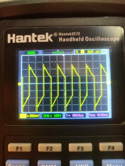
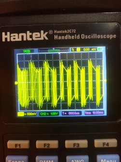
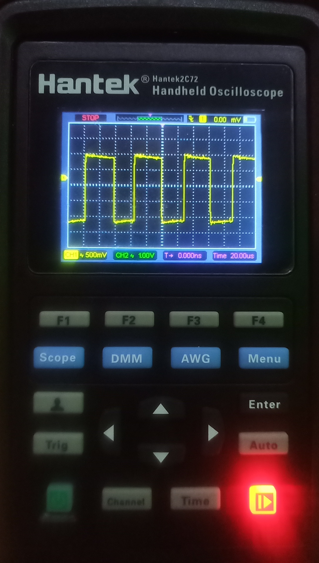
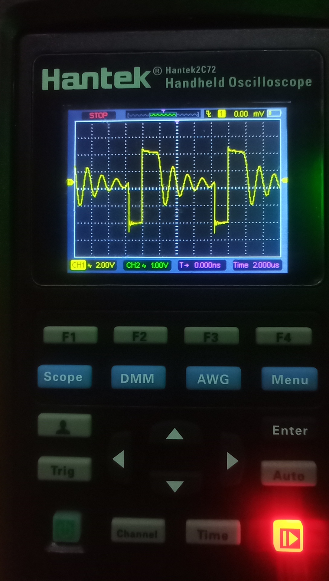
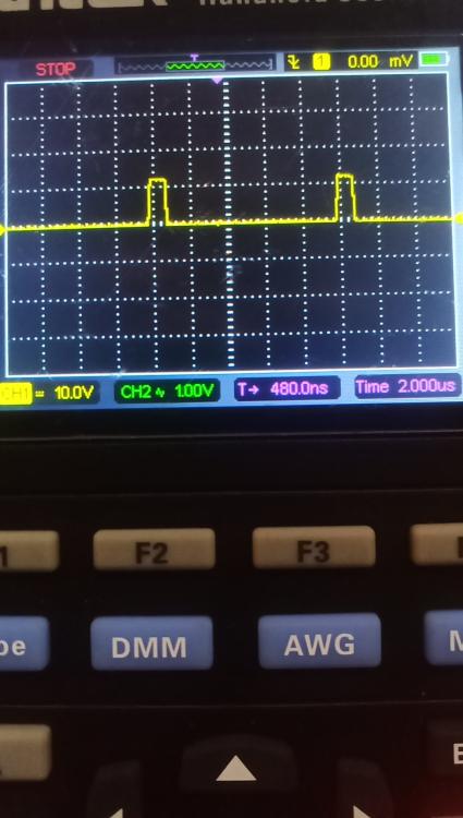
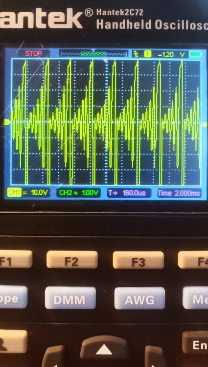
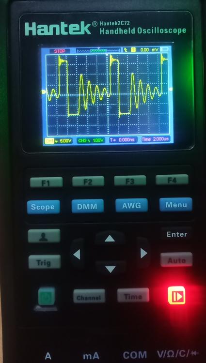
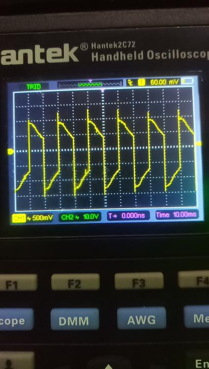
Hi. At 20μs it is exactly as you say. And the 12v output source on the transformer is trapezoidal with oscillation. also measured transformer tx7 input and output, these oscillations gradually increase. I attach a photo.


-
Hi Coulomb. You're right. The resource is designed exactly as you say. 12V is fine. Only it's not exactly Axpert but some kind of Revo II clone and it's not 100% the same in everything. The curve seems a bit better on the N side and I'm not sure at all on the L1 side of the phase. It's strange to repair (modify) something that has no damaged parts and still doesn't work properly. On the other hand, it is a pleasure to consult such a matter with someone who has such extensive knowledge as you and is still on the other side of the globe.

-
So I adjusted the excitation so that it was the same for all four igbt transistors. C55 is and was present (nicely described). But it's only -5.5V/+8. An increase to the recommended approx. 15V is not realistic without total adjustments to the source. I have one more question. What is the approximate self-consumption of an inverter powered by a solar panel? 20, 50, 100W, More?
-
I know the dangers very well, I have been dealing with electronics for a very long time and I am an electrician by profession. However, it doesn't solve my problem. do you think that if I complete the components according to the channel with 5-a+7v, the problem with excitation will be eliminated? I can basically also use an external source for the bus voltage with limited current for safe testing. I have a 30v 10A power supply.
-
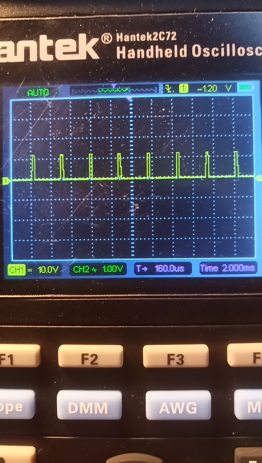
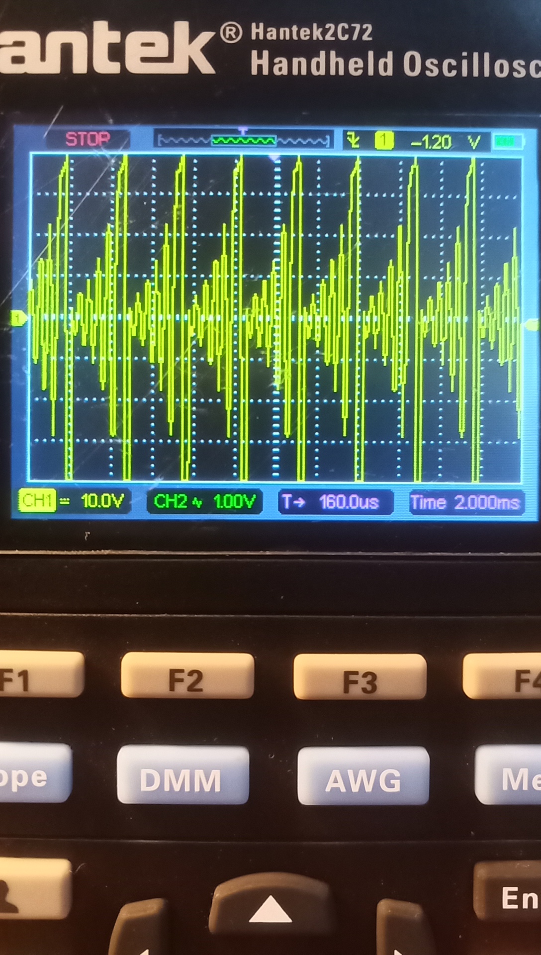
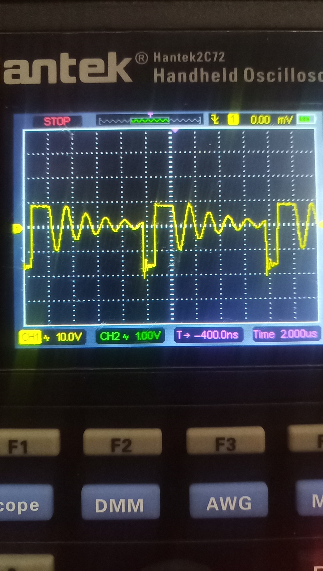
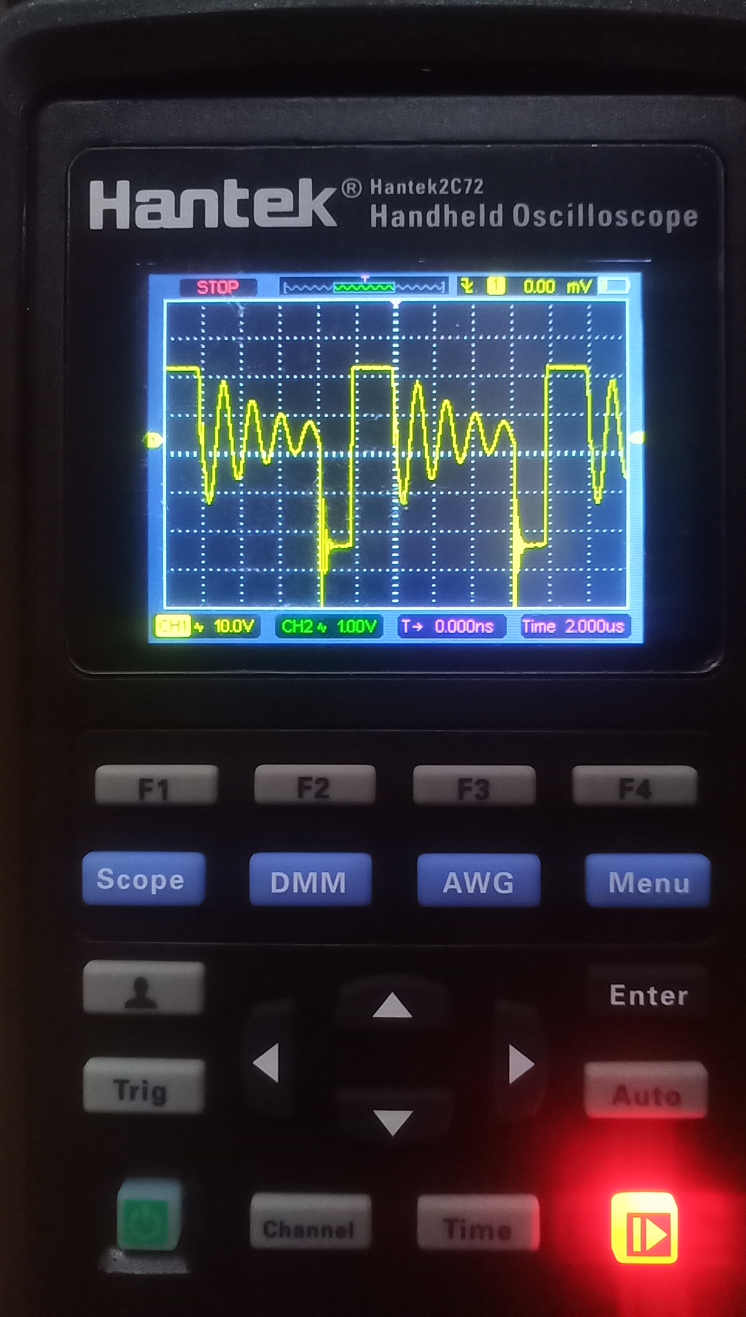
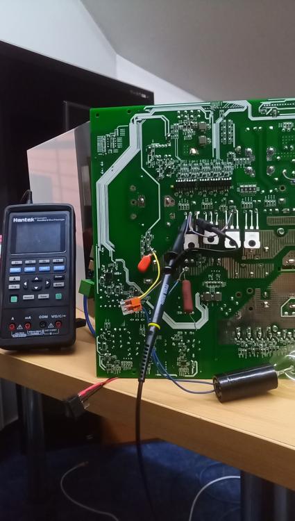
The transistors are now tentatively just grabbed from the other side and connected via a light bulb for protection. I measure directly with a hand-held oscilloscope. See photo.
-
These parts were always missing. It's so original. I am the first to disassemble the converter. It was working normally and properly before. It's mine and it worked for about a month until I connected the ground and input from the panels. Is there a pattern of the correct signal (picture)?
-
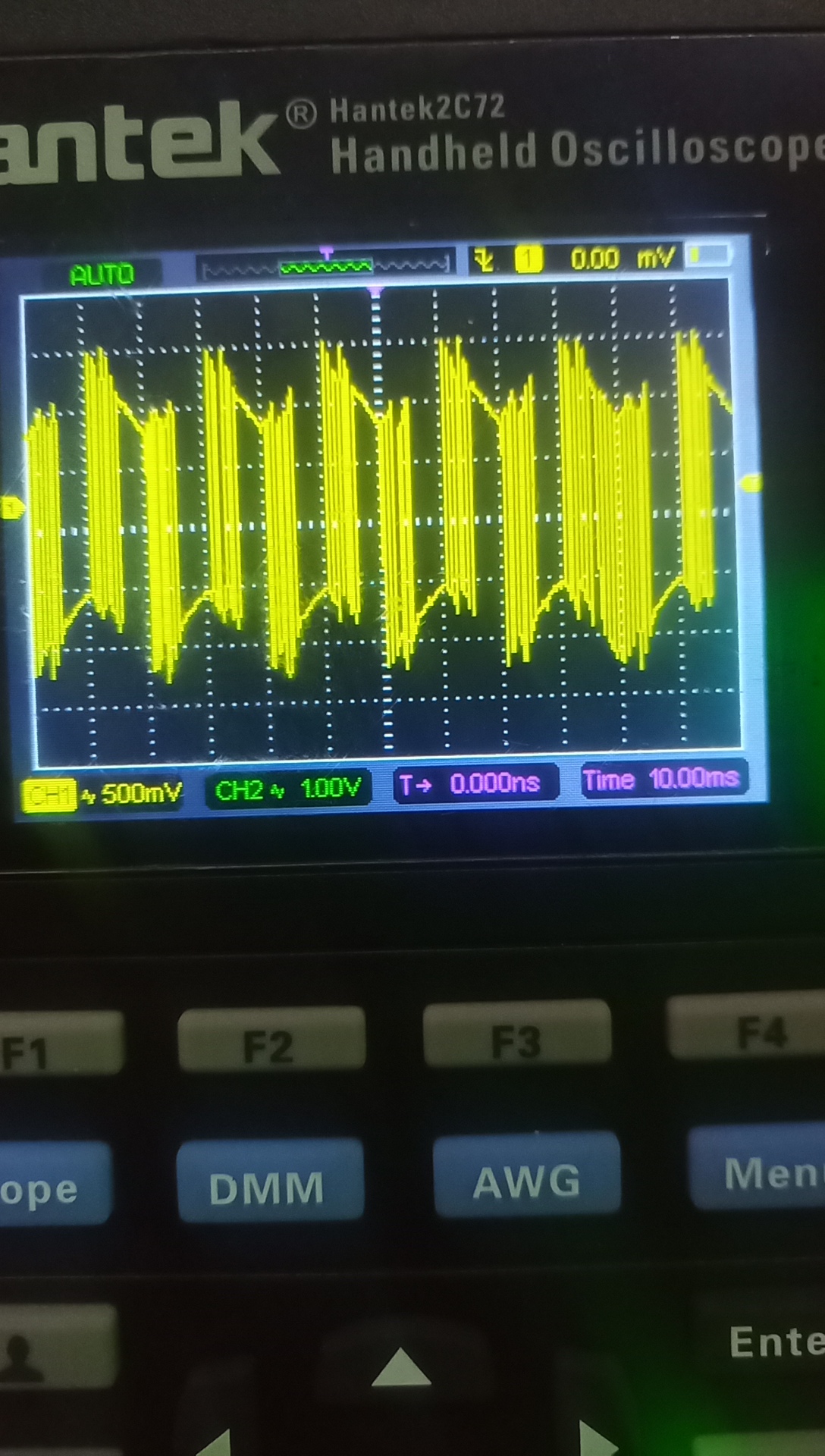
So measured. Twice -5.5v/ +7.7v QB2,QA1 and twice 0/ 12.1v QD2,QC1. R21, ZD4, C55 is not originally installed on the board. Strange. According to this wiring it works correctly. If they were to function the same, these components would have to be supplemented. Igbt transistors are FGA60N65 in my case. No error found.I know how the first problem with the converter arose. It was active over the network at night, and when replacing the fuses with another, better type, I connected the input cable of the panels. Panels de-energized and disconnected. I checked all excitation transistors as well as voltage +12, -12v, 5v. Everything seems fine. I replaced only 4 Igbt transistors. The only other thing I can think of is some connection between the low voltage and the high voltage for the Igbt.I am measuring igbt transistors G-E and the collector is connected via a 230v40w bulb to protect the transistors. Furthermore, the 20 micro F capacitor at the output is also removed to allow the load. It is clear that the output will not be a pure sine wave, but it should not affect the input control signal. The only thing I can think of is the quality of the new transistors. They are from Aliexpress. Could they be of poor quality and causing the problem of burning and shorting the Igbt?Hi, I also have a Revo VM II 5.5kW and I have a problem with the Igbt transistors that keep going out. There are four dc/ac outputs. I checked almost everything. The first two have a different sequence of wake-up signals and I don't know if it's OK. Can you confirm the correctness of the difference between these signals? Or measure these signals on a functional converter? Thanks.