Skipbidipop
Members
-
Joined
-
Last visited
Everything posted by Skipbidipop
-
the actual voltage was around 3.59.. because, as I said, the voltmeter on the charger is showing little bit more ... it's just not precise.. when I measue the voltage on the charger it's around 3.59 and there is couple of mV on the wires from charger to battery I disconnected the charger and left the cells in parallel for over 8 hours now.. the voltage now is 3.500V - 3.501V, but the deviation of 0.001 volt is probably because of the instrument I'm using (poor battery in it and very bad test leads/wires - its UT61E btw) Is this OK, expected ?
-
I have changed my wires for parallel/balance charging to copper strips and that has changed the current quite a lot.. finally my weak charger can give full current (10.2A) and go into constant current mode.. previously I had just wrapped and torqued regular electrical solid core wire around the posts ..and the resistance was too large so I was getting only around 8A .. so now I don't have to worry about voltage drop on the wires because it has almost none.. <0.001V on the wire to the charger and 0V on the copper strips Yesterday it was charging at 3.47V, the whole day.. for a long time the voltage didn't change.. and during the evening, in just couple of hours the voltage raised from 3.47V to 3.58V .. and now(few hours later) its still in CC mode at 3.65V and I expect to see transition to CV mode soon (voltmeter on the charger is showing a little bit more than it actually is).. is this normal? Is this that flat part of the curve transitioning to vertical part ? ___ edit: I just watched this video and I think this is my answer .. when I compensate for voltage drop in wires from the charger and the fact that my charger voltmeter is not precise
-
52°C ??? 🫠 I know this is South African forum.. are you from there also ? Actually I don't know how I ended up on this forum.. I guess while I was googling, this forum came up a lot, so I decided to join 😁 For me it's strange to think that south half of the world celebrates new year in the summer and have the longest day of the year in December ..and I am talking about how I'm afraid that my batteries will be damaged around 0°C while you have 52°C 😅 I know this is off-topic but it's interesting btw, I also think in "12V math" all the time, so no problem 😆
-
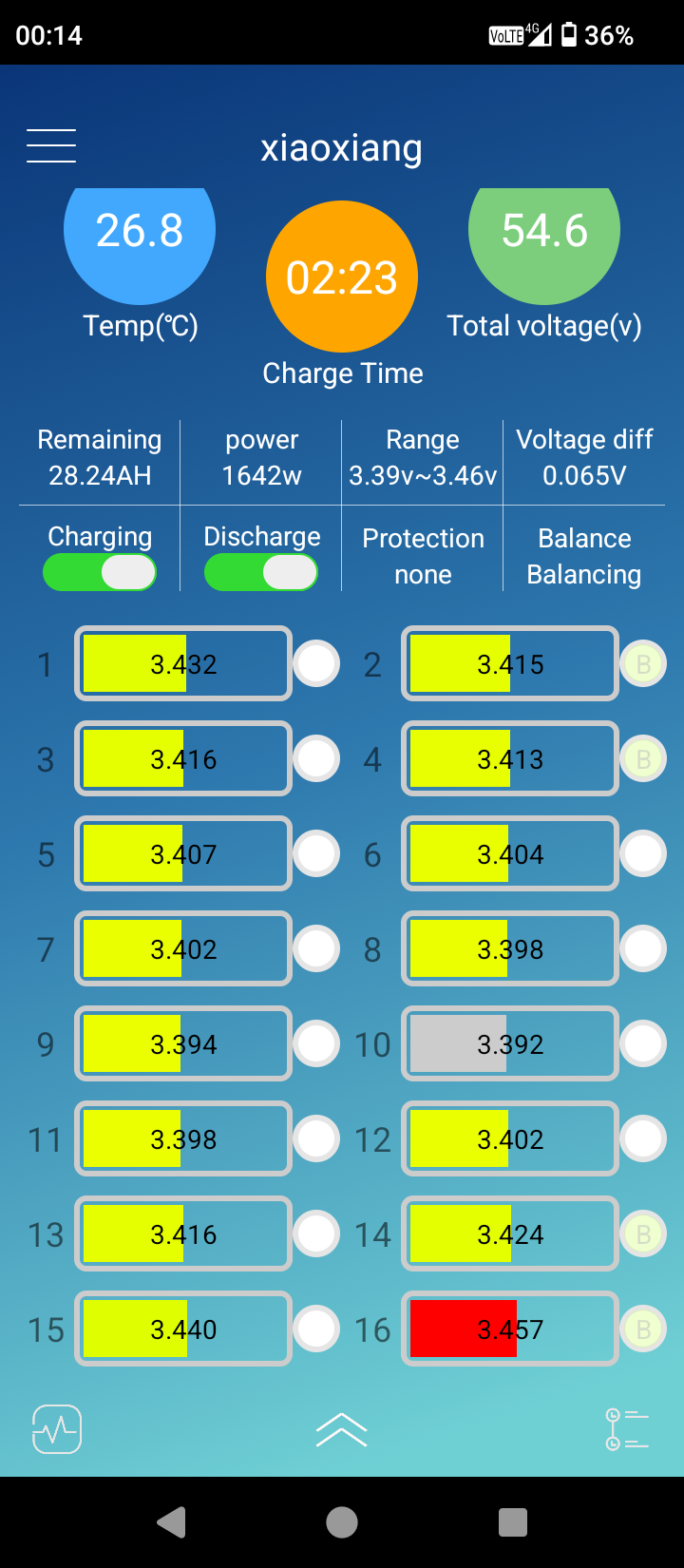
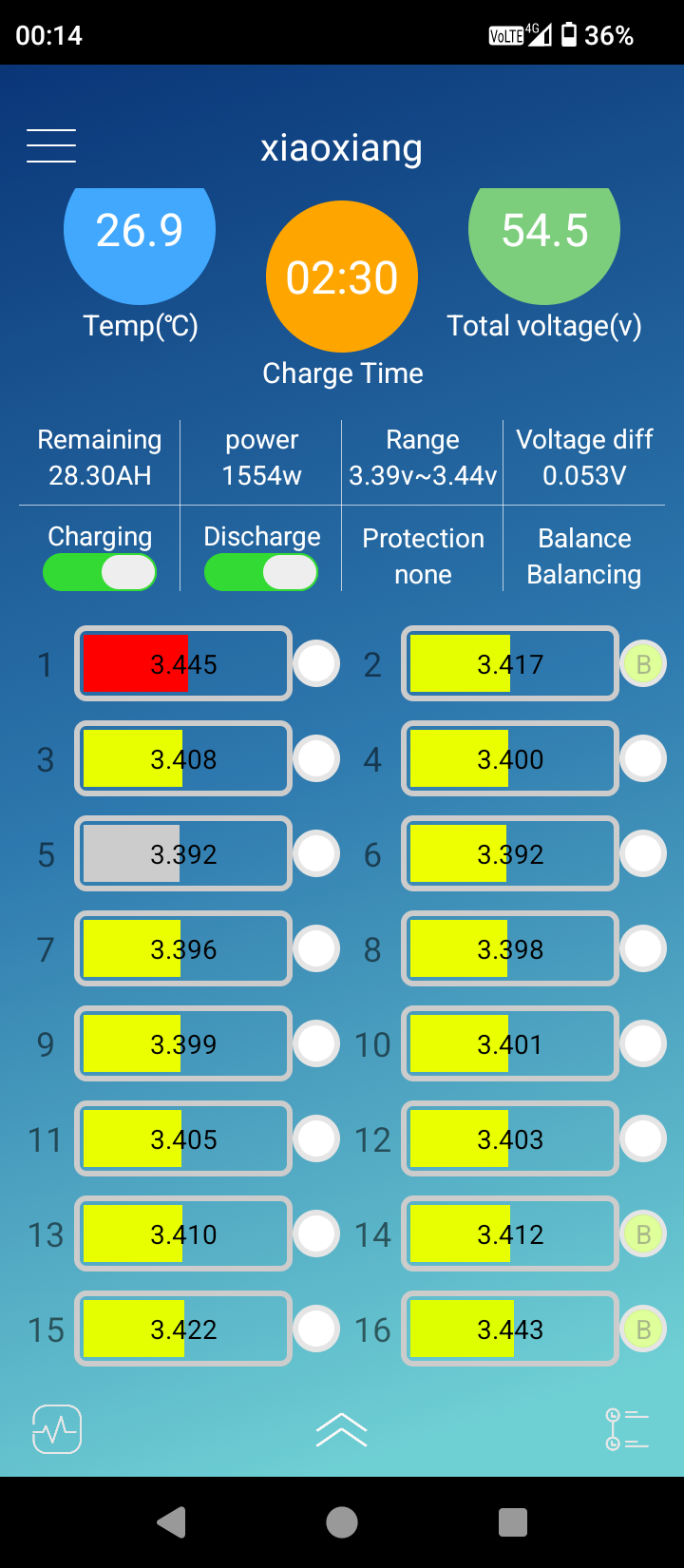
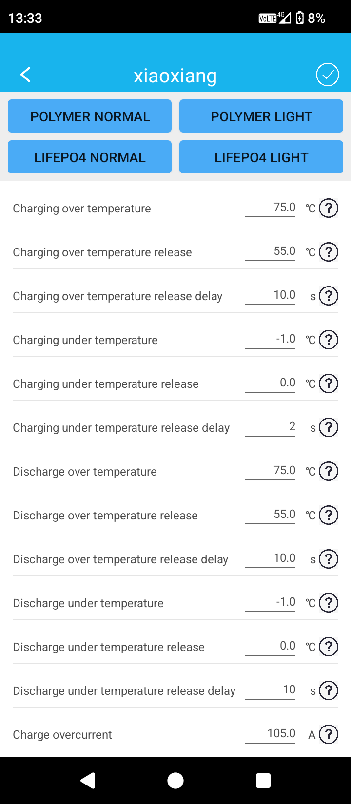
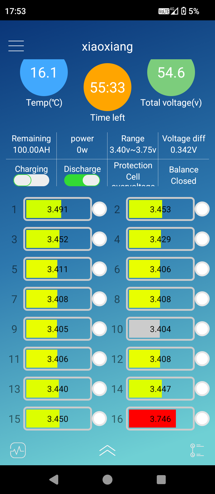
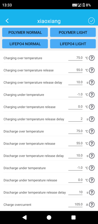
I got to around 3.45 for most of the cells except for that last 16th cell, which got to over-voltage protection and turned off the charging.. now I am slow balancing at around 8A again so now this one cell got to more than 3.6V couple of times and sometimes even to 3.7 for few seconds.. did this damage this cell maybe ? In the app there is this parameter called "overvoltage release delay" and I misinterpreted it and set it to 10sec.. and by default it is set to 2sec .. you can see a screenshot of my settings couple of posts ago
-
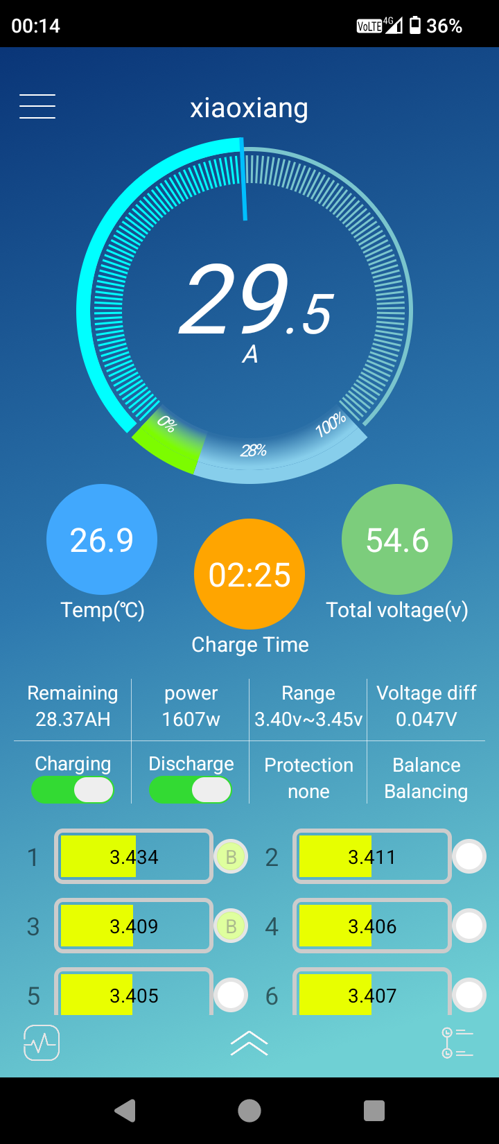
I have increased the current to 30A


-
Why less with the BMS? You mean to 3.45 while in series(with BMS) and then to 3.6 when top balancing in paralel?
-
Thank you all for help.. I'm home now, and took the battery with me.. looks like I'll have to use lead-acid for few more weeks there .. good thinking for not taking those 200kg batteries out of the basement because my back would say "no" if I had to carry them down there again 🤣 They have been balancing (passive I guess, through the BMS) whole day today, while I was reconnecting my lead-acid back and traveling home.. and they are a bit closer to each other now.. when the BMS stops charging I will connect them in parallel again and top balance with my slow charger I'm charging now with 20A.. Should I go higher? So, should I go to 3.6 or 3.625, 3.65V ?
-
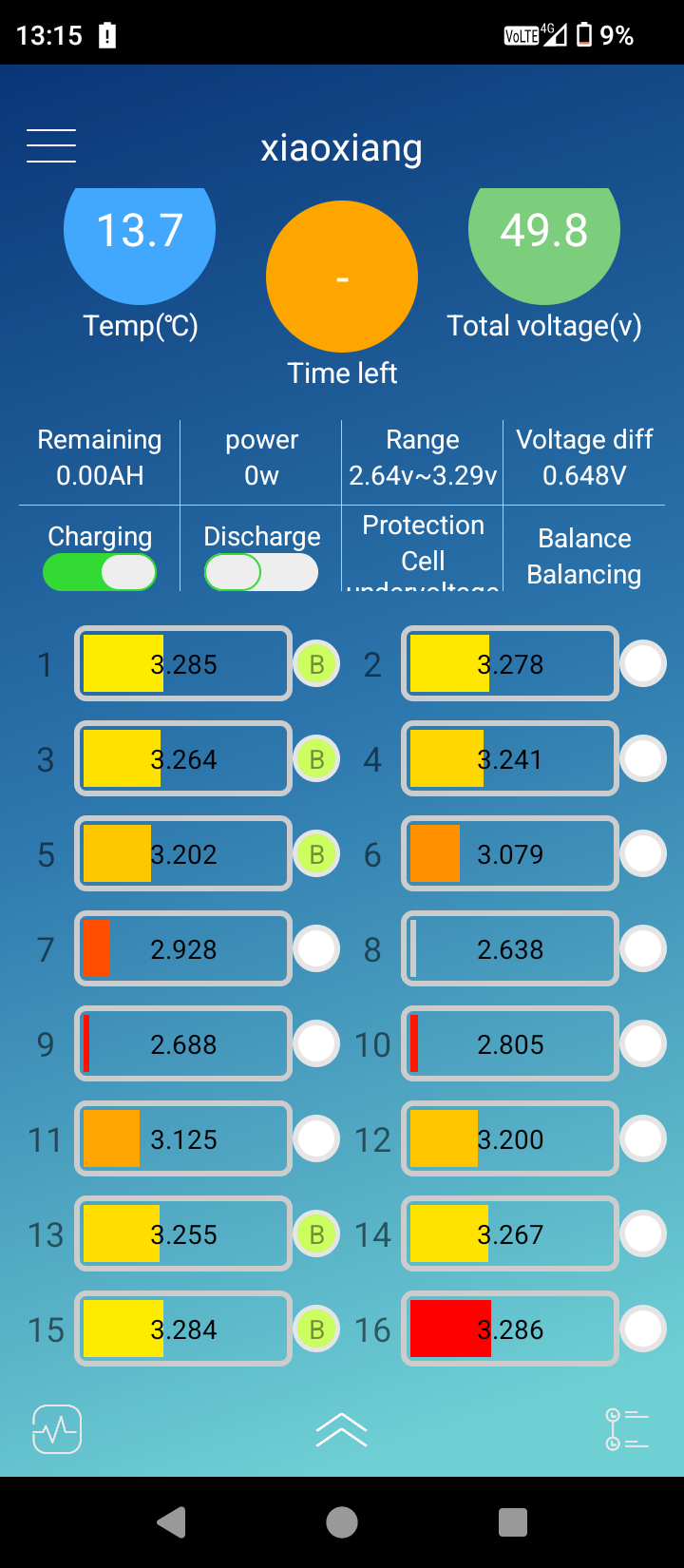
It won't charge.. I guess because of the 8th and 9th cell are below 2.7V


-
Ok.. I will try that .. Now the cells are all at different voltage because I used them during the night and early morning..I have no power here other than this But the cells were at the same voltage before the first charge.. within 1mV..so I don't know how it will helpHy all.. I have connected the battery to the inverter.. And I have a problem

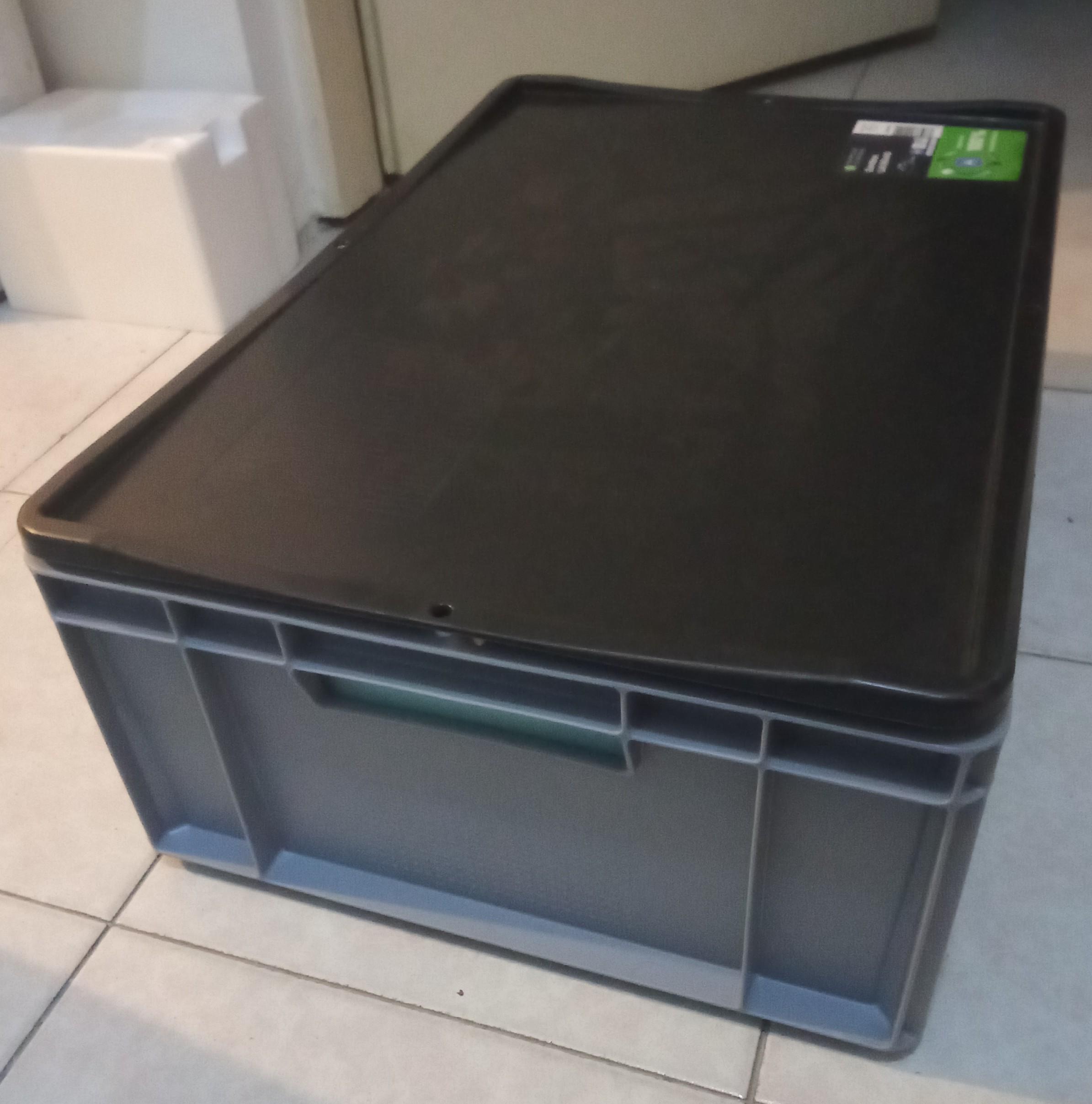
 Where are you located? I don't know the answer.. in fact, I don't really understand what exactly are you asking? Are you saying that the City limits your power production you are pushing into the grid? What is "CB" ? I'm just interestedStill charging around 8A.. this will take days.. 🤢 .. I'm thinking again about connecting the cells in series(with or without BMS ?), charging it with a solar inverter-charger(5.5kW) over the grid, to almost full.. and then again connecting it parallel like it is now, and charge/balance to full. Also, in last few weeks I started working on quite a few Li-ion packs.. for scooters and bicycles .. so I may invest in a charger/load tester like Steve87 has.. or something similar.. I found one in EU for around 275€ with shipping .. still seems a bit expensive, but even on aliexpress I can't find it cheaper.. I think this one is a pretty good one.. 40A, PC software, etc https://batteryfinds.com/product/zketech-ebc-a40l-large-current-lithium-battery-capacity-tester/ Can somebody recommend something else? Preferably cheaper ___ I bought cheap plastic box with a lid.. and lined it with fire retardant styrofoam.. this should help contain some heath during winter so it doesn't go under 0 deg C ..in summer, I can always take the battery out. side panels are shorter because compression fixture can't fit otherwise __ Also, I made a simple 3D printed brackets for mounting the BMS: here is the file.. it's a spinoff of another bracket uploaded on thingaverse JBD_BMS_Bracket.stl


 I have finally connected the charger.. I have compressed it by feel with hand.. and I'm done with compressing.. as many say it is not worth the effort.. If I ever build another battery I will just compress by feel again I returned the big torque wrench and bought a smaller one, for bicycles.. still not low enough torque range.. this one is 2-20Nm +-4%.. but at least I can torque down the terminals and busbars now 😁 I connected all cells in parallel with household installation wire.. solid core, I think 2.5mm.. no wires are touching each other.. and the charger poles are on the opposite sides as you suggested And from the start it was about 3A only.. my shitty TEMU voltage source came with very bad wires.. there is around 0.12V on each wire.. so the actual voltage applied to the battery is only around 3.3V.. it will go up as current gets lower.. I hope this will be OK.. I don't think I can damage the battery this way.. I don't want to increase the voltage on the charger to compensate for drop in wires __ edit: I realize now how stupidly long it would take to charge the battery at 10W.. I'm thinking 20 days or so.. I'm in search for better wires right now __ 2nd edit: new wires.. charging at 8A now

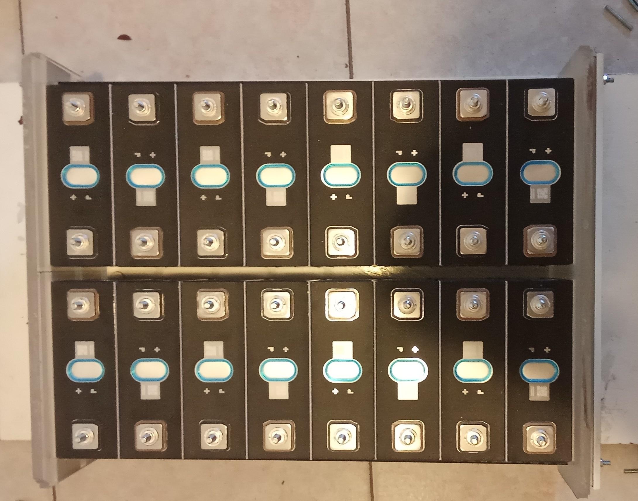
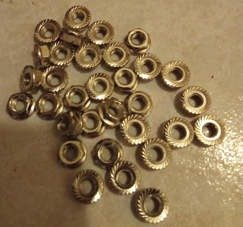
 I bought a torque wrench today.. but I just realized how little torque is actually needed for 3000N of force.. spread out on 4 bolts.. one can easily over tighten it just with a hand screwdriver.. and I now have a wrench used for tightening car wheels and such😅 .. minimal torque setting is 28 Nm 😅 Couple of posts ago we calculated it needs to be just 0.6 Nm for 4x 4mm bolts.. now I have 6 bolts, that is 0.4 Nm.. is this correct ? It doesn't make much sense to me.. that is only 0.04kg=40g on 1m .. one can easily tighten this with fingers.. am I supposed to divide 3000N by 6, for six bolts ,,or each bolt must press with 3000N ? 40g is 2 packs of cigarettes 🤔???I have assembled the battery, but didn't torque it down yet.. as you can see I have subscribed to compressing after all I used 8mm plexiglass on top and bottom sides ..and some aluminum profiles (painted white in the photos), to compress the battery.. and 2 sheets of cardboard (~1mm) between every cell. I had to make some space between the two rows because the busbars don't fit on terminals if they are together.. I think this is actually good because I think I need to add 2 more threaded screw bars in between the 2 rows because when I started to tighten the nuts there was some bending in the aluminum profiles and the plexiglass.. I used straightedge to check as I was tightening.. is this OK? Here are some pictures: Also.. I don't know what torque to use on the terminals.. I've found spec for compression in datasheet(1500-5000Nm) but nothing for terminals.. is 5Nm enough?

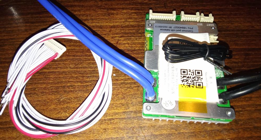
 yes, thank you.. I think we talked about this in the beginning of this thread My BMS can't be connected to my inverter as it doesn't have rs485.. only UART(TTL 5V I guess) and bluetooth.. That's why I said I plan to make a converter for this.. because those BMSs are really cheap and good.. InverterBMS from the same manufacturer is about 150% more expensive I hope I can set the BMS over bluetooth to not charge under or around 0°C.. it does have 2 external temp sensors after all _____ Thanks.. good idea.. almost any problem has an online calculator solution 😅 ..one just has to remember to search for it So, I put in 4mm as bolt major diameter and 750N of force because it's 1/4 of 3000N = 300Kg and I will have 4 threaded bars... and I get 600Nmm = 0.6Nm for torque Does this make sense ? 1/4 for each threaded bar ? Is my bar too thin? 4mm for 75Kg ?thanks.. I've seen this video yesterday.. and a later video from Andy, also about compression.. basically, he still argues that compression is not needed due to cell's calendar ageing will happen well before you reach cycle damage... but, he also said that it does increase cycle life nevertheless.. it's just that most people will not be able to use it .. as I understand this.. what compression also does is it squeezes out the gasses that form in first couple of cycles.. and thus prevents this kind of damage.. if you miss it from the start, then compression will not help you at all here is the video as I think my cells are indeed grade A and were not charged or cycled in factory, it might be worth compressing them .. just because I might by cycling my batteries more than normal users ___ here is the spec/datasheet of my cells: REPT CB56-100Ah 产品规格书.pdf there is no spec for torquing the screw nuts on the terminals or compression.. what do you recommend ?ok.. this is a good idea.. I wouldn't think of that myself.. I know of this but always forget .. thanks why don't you compress your cells ? I thought it would give you more life out of your battery, stop the delamination, etc.. I thought this was standard practice So, I should not expect swelling if I just charge-balance them without compressing? I can compress them later? ___ yes, my first build with lifepo4.. only lead-acid before this .. I can already see it is addictive 😅🤣 and quite fun.. only if shipping was fasterI have 30V 10A DC variable source.. its a switching mode power supply .. that shouldn't be a problem? What voltage should I set on the charger ? Should I compress the cells before charging/balancing ? I'm afraid that the cells will swell up while balancing on the charger .. on the other side, if I compress them I would like to arrange the electrodes in alternate positions, so that I can connect them with busbars in series afterwards.. then I can't use the same busbars to connect them in parallel for balancing.. what should I do ?yes.. that makes sense .. whats the best way to top balance ? I don't have grid power at the house where I will be installing this battery.. but here, I have grid and 48V hybrid inverter.. Can I just charge the battery whit this inverter and then connect all the cells in parallel to balance them?also, the BMS is here its the Jiabaida SP17S005 V1.6 with bouetooth and UART .. its 100A I've seen some open source projects with PYLON protocol on arduino.. I plan to make a converter from UART to RS485 for communication with my inverter.. we'll see what will be of that.. I'm still learning about that
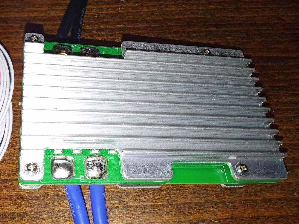
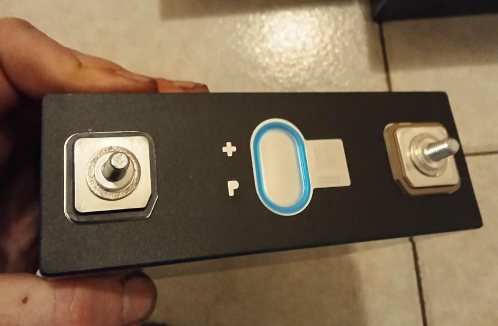
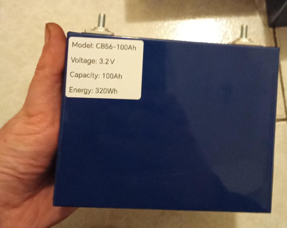
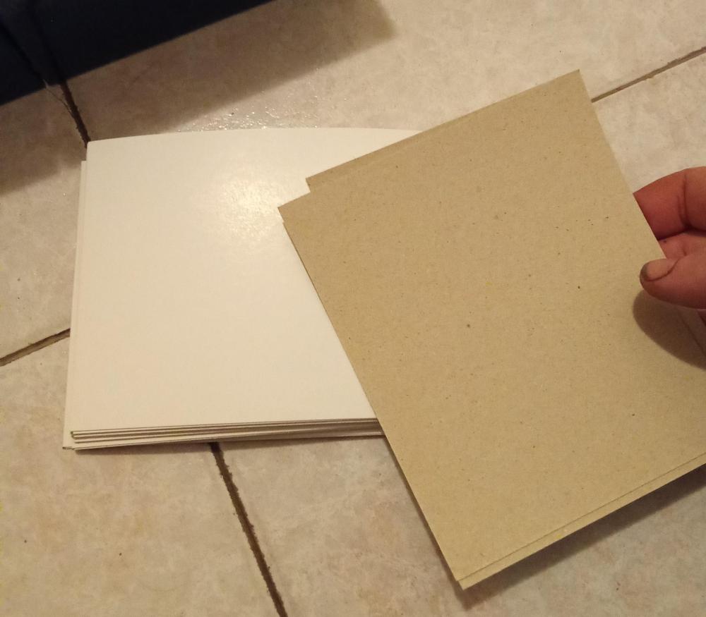
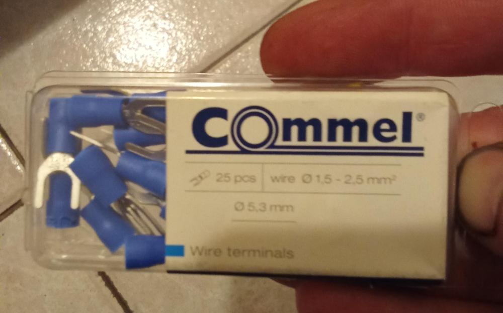
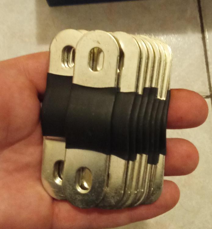
 I finally got the cells..: REPT CB56-100Ah ... from NKON (eu.nkon.nl) .. they look nice.. no swelling .. all within 0.003V .. so I guess no need for top/bottom balancing ?? here are some specs: Typical Capacity: 100Ah 25±2℃,0.5C/0.5C Typical Voltage: 3.2V 25±2℃,0.5C Typical Energy: 320Wh 25±2℃,0.5C Operating Voltage: 2.5-3.65V 0℃<T≤55℃ || 2.0-3.65V -20℃≤T≤0℃ Standard Discharging Current: 50A 25±2℃ Maximum Continuous Discharging Current: 100A 25±2℃ Maximum Discharging Current: 250A 25±2℃@50%SOC,10s Standard Charging Current: 50A 25±2℃ Maximum Continuous Charging Current: 100A 25±2℃ Maximum Charging Current: 150A 25±2℃@50%SOC,10s Operating Temperature: 0℃≤T≤55℃ Charge || -20℃≤T≤55℃ Discharge Also, I got nice plated busbars, with each battery 2pcs.. and I bought 4mm threaded bar for compressing the cells and I plan to use thin hard cardboard between the cells for insulation.. and I bought 5.3mm terminals for the BMS wires. I will use 8mm plexiglass on top and bottom for compressing the battery What do you think?
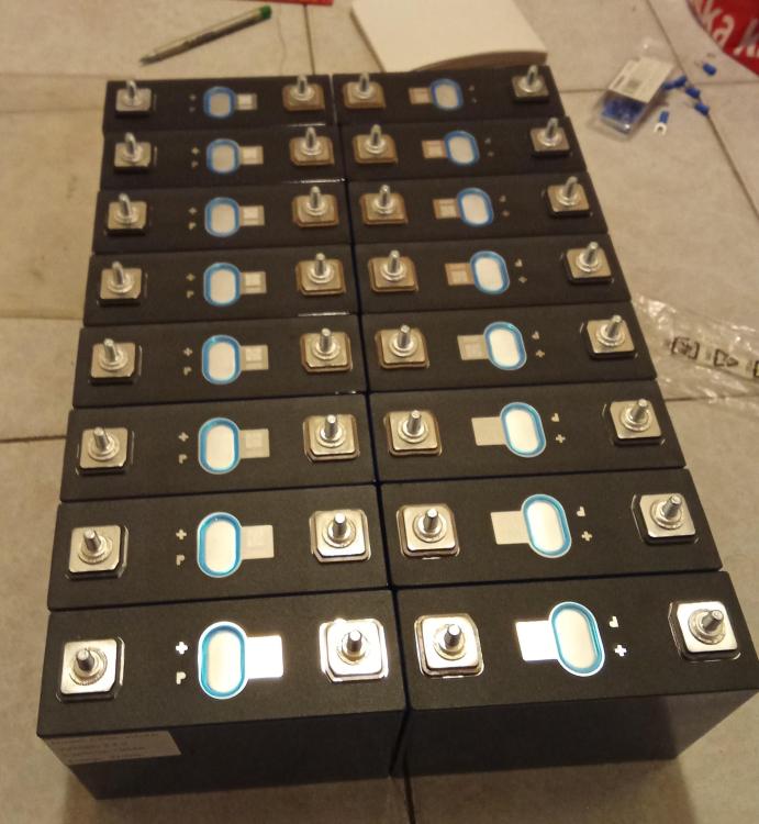

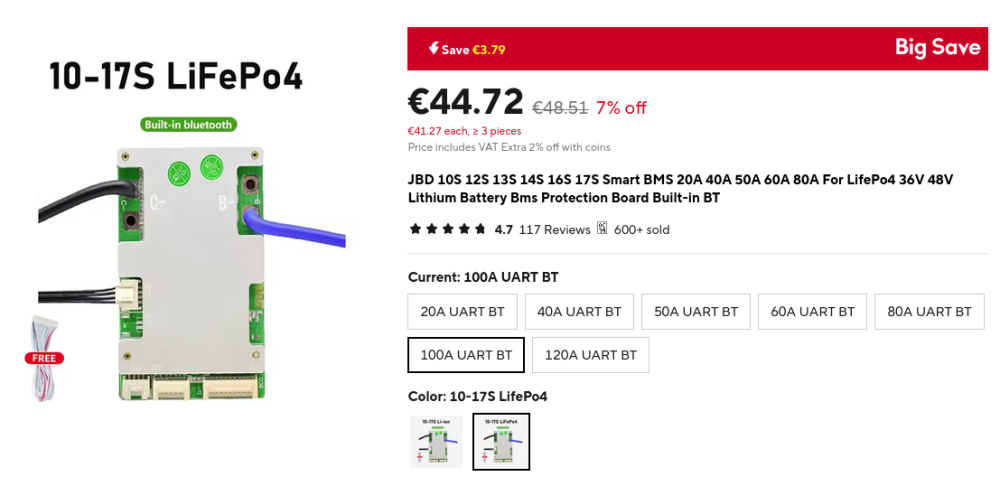
 there are TTL to RS485 converters available .. would that help? My inverter supports PYLON US2000 Protocol 3.5 Version and Standard communication Protocol form inverter supplier. And also it supports Lithium battery without communication I don't understand what would the inverter need from the battery BMS anyway .. can you explain? Does it only get the battery BMS settings, like max charging current, float voltage, etc.. and then sets the inverter parameter to those settings? .. or does it do something else? If that is the only thing it does, than I guess I don't really want it.. I think it's safer to just set the parameters in the inverter and the BMS separately .. then the com between them won't be a possible source of error.. isn't that right? So for example, if the BMS fails to limit the current the inverter would still not take as much current.. and if the inverter would fail to limit the current, the BMS wouldn't supply it _____ My inverter has a WiFi module and I can see the status and configure the device remotely.. this is great and works OK.. If I somehow manage to connect the BMS to the inverter, is it possible to view the BMS settings and status over the same WiFi ? It would be great If the inverter could request such data(eg. voltage of each cell, battery temperature, etc..) from the BMS and display it in the same appI bought these batteries: https://eu.nkon.nl/rechargeable/lifepo4/prismatisch/rept-cb56-100ah-100a-lifepo4-3-2v-a-grade.html REPT CB56 - 100Ah I hope they will be good, we will see what I'll get.. should be here in 2 weeks ___ I also bought this JBD BMS: https://www.aliexpress.com/item/1005004862569135.html?spm=a2g0o.order_list.order_list_main.5.3e6b18025wSEX4 I used this BMS for an electric scooter before, and I used the Bluetooth com for setup on my android phone.. but is says here it has UART com too.. Did anybody use this UART before? Is it RS232 or 485 ? I know I can do the settings setup over computer, just like over Bluetooth on android .. Can I somehow connect it to the internet and see the settings and information remotely ? What can I do with it? Can It be used to connect to my inverter? I know there are actual 'Inverter BMS's' from JK.. you get a com board with rj45 connectors, some LED signaling and optional LCD and what not.. but it is more than double the price of this one What actually does the inverter get from this? What is this communication used for? Why does the inverter communicate with the battery at all it it only charges the full battery pack and not individual cells?