


HandySmurf
Members
-
Joined
-
Last visited
Everything posted by HandySmurf
-
Quick update on this. I managed to get comms going between the inverter and battery. I can now see the charging current changing dynamically depending on state of charge (lower SoC higher current and vice versa). Charging voltages were also changed when I switched over to PYL. Error with the solar generation stopping completely has gone away. Happy. Thanks for the support!
-
Quick update. After reducing the charge voltages the error hasn't re-occurred. Happy days. Next step is to get comms going between the inverter and battery. I want to do this in any case as it seems to be the best long term solution. There are still random instances where PV generation drops to zero (even though it is sunny), but so far generation has always resumed again shortly after. I haven't been able to identify a pattern. Sometimes this happens with load change, but other times not (example below). It would be great to get this resolved, but it doesn't really seem to be a significant problem as generation recovers shortly thereafter. Unless I'm missing something? Thanks for all the help!


-
Thanks @Shadders I'll give those voltages a try. I changed to the following FYI: I've read though various posts to find the correct pin-outs, but there's a lot of contradicting info. I understand I need to change the battery DIP settings to 1-0-0-0 to change baud to 9600, restart the battery and then change parameter 5 on the inverter to PYL. Axpert King 5000 to UP5000 Can you please assist with the cable pinouts? This is what I found: I also found the following:


-
Thanks for the information and help @Shadders ! It's appreciated. It has happened 3 times in the last week. Each time just after the battery reaches 100% SoC. Load remains fairly consistent during this time. There isn't direct communication between the inverter and the battery. I use Solar Assistant to manage the system - Solar Assistant sits between the Inverter and the Battery. Max Charge current is currently set to 30A. What would you recommend I reduce this to? 20A? I'm only able to adjust the Battery float charge voltage (currently 53.0V) and the Battery absorption charge voltage (currently 53.2V). I don't see the Bulk charge voltage. Looking directly on the inverter parameter 26 is set at 53.2V so it seem like Solar Assistant uses Battery absorption charge voltage also for Bulk. What would you recommend I adjust these voltage to? Battery float charge voltage to 48.8V and Battery absorption charge voltage to 53.0V? Additional information regarding cell balancing. I can see the following information on Solar Assistant. I've seen some fluctuation, but the difference between highest and lowest cell voltage stays under 50mV (typically 30mV or under as seen below). Would this indicate an imbalance or is this normal? From what I found in previous posts this seems OK.


-
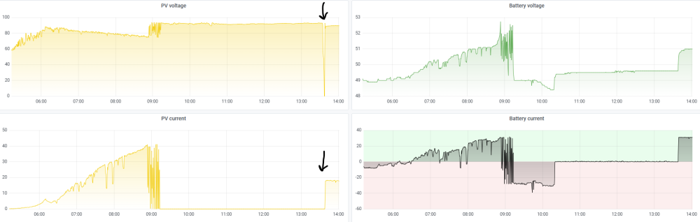
Additional information. I quickly popped home to see if I can see any obvious errors, start troubleshooting etc. I pulled all the PV fuses in the combined box. PV voltage dropped as expected. After a minute or so I started reconnecting (closing fuses) one string at a time. PV voltage increased as expected. Shortly thereafter I could hear a distinct click coming from the inverter (sounded like a relay engaging) and then the PV current started to increase. Battery started charging (ie system operating as usual) Ignore the change in load - that's just me switching off the pool pump. PV voltage dip when I pulled the fuses. PV voltage and current increase shortly after I reconnected. Don't read anything into the system is only generating +- 1.5kW PV -> that's due to the limiting the maximum battery charge current / power to 30A. Once the battery reached 100% SoC the SCC started behaving strange again (not the dips below), but then stabilized. I'm on firmware 71.97. I was under the impression the SCC firmware issue described below was resolved on 71.94 and above. What is also strange is that the system has been working 100% OK for the last 2+ years.


-
Hi All, I’m hoping someone on this forum can provide advice… I’m experiencing a strange problem where, just after battery SoC has reached 100%, PV voltage is still OK but PV current drops to zero. Some background on my setup. Synapse 5.0K+ inverter and Synapse 4.8kWh battery with 10 x 420W panels in a 2S5P configuration. System is managed by Solar Assistant. According to the datasheet & label on side of inverter the MPPT specs are as follows: Min Solar Voltage 40Vdc Max Solar Voltage (Voc) 145Vdc MPPT Voltage Range 60-115Vdc Rated Current 80A Firmware version 71.97 Model name KING-5000 Model number 35 Solar panel spec is as follows: 420W monocrystalline Maximum Power Voltage (Vmpp) 42.50Vdc Maximum Power Current (Impp) 9.89A Open Circuit Voltage (Voc) 50.50Vdc Short Circuit Current (Isc) 10.54A Installation is 10 x panels in a 2S5P configuration. This should give me a theoretical: Total max power of 4200W (slightly over the 4000W rating, but well within the 15% over-rating rule of thumb) Open Circuit Voltage of 101Vdc (well under the rated max of 145Vdc) Max Power Voltage of 85Vdc (within the 60 – 115 Vdc range) System has been working without problem since August 2023. Last week something strange happened… Solar generation started as normal in the morning. PV voltage and current increased and batteries started charging. Once the batteries reached the required SoC the system switched to SBU as it should. Once the batteries reached 100% SoC the strange behavior started. PV volage is still OK, but PV current drops to zero. There are a few spikes of PV current, but not for very long. PV current then drops to zero and stays there. PV voltage is still OK. After a while the battery obviously discharges to the level where Solar Assistant switched back to SUB / Grid mode (as it should) I was out of town so couldn’t do much investigation. The next morning solar generation started as usual and has been working OK for the last few days….until today when it happened again. It’s almost like the MPPT can’t find the max power point and then rather just shuts down. Has anyone experienced this before? The really strange thing is that it did something similar yesterday (I only noticed it today). There are the same PV current drops just after the battery reaches 100% SoC, but then it continues as normal after. Other days don’t have these PV current drops. Any help of advice would be greatly appreciated!


-
@Coulomb Thanks for the reply. Easy enough to do (can just pull the fuses for one of the strings in the combiner box) to test. I would be surprised if this was the issue though as the PV power (power, voltage and current) at this time is well within what the MPPT is supposed to be able to handle. Unless the spike is too quick for the monitoring software to detect. I'll try this when I get a gap and let you know.


-
After a bit of playing around I found that this only seems to happen while in SUB. When in SBU the MPPT seems to behave itself. We had a nice sunny day on Saturday so could test without having to worry about cloud cover influencing results. Ran SBU the whole day except the period from 10h08 to 10h34 when it ran SUB. Can clearly see the strange MPPT behavior in this window.

-
What is strange to me is that the PV output is fairy stable as long as the load is larger than the PV supply. In the image below you can see that the PV supply increases as the morning sun gets brighter. As this time the supply is fairly constant. As soon as the PV exceeds the load this behaviors starts. I expected the PV to chase the load and then once it's in a position where it matches the load is will stay there constantly. It's almost like it overshoots and then overcorrects.

-
Hi @Jacques Ester Thanks for the reply. Is the load really that erratic? Looking at the image below the load (blue) is fairly consistent at 1kW, but the PV (yellow) fluctuates between 706W and 1.51kW.

-
Update. The plot thickens. As soon as utility supply falls away (loadshedding that started at 12h00) the PV supply smooths out even though load is very low (I have a contactor that drops out the non-essential loads during loadshedding). I still don't understand why this is happening, but is it possibly related to the SUB configuration?

-
Hi All, Finally connected PV Wednesday late afternoon… Some background on my setup. Synapse 5.0K+ inverter and Synapse 4.8kWh battery with 10 x 420W panels in a 2S5P configuration. Power source/priority configured as SUB. According to the datasheet & label on side of inverter the MPPT specs are as follows: Min Solar Voltage 40Vdc Max Solar Voltage (Voc) 145Vdc MPPT Voltage Range 60-115Vdc Rated Current 80A Solar panel spec is as follows: 420W monocrystalline Maximum Power Voltage (Vmpp) 42.50Vdc Maximum Power Current (Impp) 9.89A Open Circuit Voltage (Voc) 50.50Vdc Short Circuit Current (Isc) 10.54A Installation is 10 x panels in a 2S5P configuration. This should give me a theoretical: Total max power of 4200W (slightly over the 4000W rating, but well within the 15% over-rating rule of thumb) Open Circuit Voltage of 101Vdc (well under the rated max of 145Vdc) Max Power Voltage of 85Vdc (within the 60 – 115 Vdc range) I’ve noted strange MPPT behavior (or at least not what I expected) where the PV power output seems to be very erratic/unstable when the output the PV can provide is higher than the load (example 09h00 – 09h05 and again 09h32 onwards). Example below: Early morning when the sun isn’t yet fully on the panels the load (idle load + pool pump) is higher than what the PV can produce. MPPT power output is relatively stable (doesn’t jump around as much). No power is drawn from the battery and shortfall is drawn from utility. At least the power blending (PV + Utility = Load) on the DC bus seems to work. At 09h00 the pool pump switched off for 5 minutes. This is where things start getting wonky and PV output becomes erratic. My theory is that this is because the potential PV output exceeds the required load. At 09h05 the pool pump switches back on, load is higher than PV production and PV output is stable again. This continues until 09h30 when the sun is directly on the panels and the possible PV production is higher than the load. PV output becomes erratic again. During these dips the PV supplies less than the load which then results in grid and battery power being used (cost and additional wear on the battery?). Has anyone seen this before? Any idea why this happens? A similar thing happened yesterday. The load coming on and off between 08h30 and 13h30 is pool pump (switches off for 5min every hour for the creepy to stop feeling sorry for itself in a corner somewhere). The higher load from 14h30 to 14h50 is a hair dryer and again a 2kW geyser from 15h00 to 15h30 (sun no longer directly on the panels). During these periods of higher load or perhaps when load is higher than what MPPT can provide the PV output seems to be stable. I assume the MPPT is then at max power point. As soon as the load drops below what the PV can provide the PV output becomes unstable.


-
Thanks @Coulomb. I'll go ahead with PV connection then.
-
Thanks for the detailed reply @Coulomb - I did a diploma in electronic engineering about 20 years ago (with very little application since) so could at least follow most Strange and frustrating that they spec the MPPT current on the output side and not input. At least now the rated power makes more sense. Reading my OP now I realise that I wasn't very clear on where I'm reading this voltage. It is actually between the chassis GND (there is only one earth as someone on this forum previously put it ) and the PV+ that I'm measuring -21Vdc. I'm also measuring that exact same voltage -21Vdc between GND and PV-.
-
Hi All, Long time lurker, first time poster. I want to start by thanking all the contributors on this site. A fair chunk of what I know about solar/backup power has been learnt here. I’m hoping someone can help with a problem I encountered while adding PV to my existing setup. Some background. For about a year I’ve been running a Synapse 5.0K+ inverter (believe this is a rebranded Voltronic Axpert King) and Synapse 4.8kWh battery (believe this is a rebranded Pylontech) as a pure loadshedding back-up solution. Load is a dedicated plug circuit (completely isolated from rest of house) & lights (separate neutral in DB) that has relatively low consumption at around 500W idle and peaking around 1500W every once in a while. This has been running without problem for a year or so. Configured as USB. I recently added solar. Intent is to use power as it is generated (cost saving) and have battery power available for loadshedding. Will change configuration to SUB. I intent to add additional load to this at a later stage to increase saving (powered via contactor/relay that drops out during loadshedding to save battery as it is only 0.5C rated), but I will keep the load unchanged for the next 1-2 weeks as I don’t want to change too many variables at the same time. If understand correctly then, if PV production isn;t enough to power the connected load, the inverter will "blend" utility power on the DC bus up until the max 5kw rating of the inverter. If the load exceeds 5kW then the inverter will go into bypass. Intent is to connect loads so that this (bypass) doesn't happen in the first place. According to the datasheet & label on side of inverter the MPPT specs are as follows: Min Solar Voltage 40Vdc Max Solar Voltage (Voc) 145Vdc MPPT Voltage Range 60-115Vdc Rated Current 80A Solar panel spec is as follows: 420W monocrystalline Maximum Power Voltage (Vmpp) 42.50Vdc Maximum Power Current (Impp) 9.89A Open Circuit Voltage (Voc) 50.50Vdc Short Circuit Current (Isc) 10.54A Installation is 10 x panels in a 2S5P configuration. This should give me a theoretical: Total max power of 4200W (slightly over the 4000W rating, but well within the 15% over-rating rule of thumb) Open Circuit Voltage of 101Vdc (well under the rated max of 145Vdc) Max Power Voltage of 85Vdc (within the 60 – 115 Vdc range) Max Power Current of 49.45A (well under the 80A max) Panels were installed over the weekend. With fuses in combiner box disconnected, I measure between 93Vdc and 95Vdc on each of the 5 strings. With fuses closed I read approximately 95Vdc combined on the outgoing DC breaker (with breaker still open/disconnected). This is all still as I expect it to be. Before I connected the PV to the inverter I did a voltage check on all terminals (old habit – don’t want to blow anything). What is very strange is that I measured approximately 21Vdc on the PV terminals without anything connected to it. Inverter was switched on at the time (AC and battery connected; feeding load in line mode). I connected using Watchpower (BT) and there is shows 0Vdc on PV1 input voltage. This doesn’t seem right to me. Surely there shouldn’t be voltage on a MPPT input while nothing is connected to it? I don’t want to connect PV and then potentially allow the magic smoke to escape. I've attached images for reference. Please let me know if any more info is required. Any advice here would be appreciated!


