


whitehexagon
Members
-
Joined
-
Last visited
-
Regarding the replacement VMIII display, after my experience with something as simple as update firmware, I think I am going to wait until I can source a replacement board, but I appreciate all your help getting to this point. I think overall I just install another 3 x 500W panels to compensate for the heat loss on the existing 2.7kW installation. Good catch on that btw, because today cloudy again, and again hitting 2.5kW-2.7kW between clouds.
-
So I tried the 11k inverter update again using another win7 machine I borrowed, with my existing USB/RS232 FTDI adapter. No luck, and when I checked under the melted cover I can see why! (attached). So I took an old FTDI used on some arduino projects and soldered up a serial port, also no luck. But I read 3.3V might be too low, switched it to 5V, and still no luck, just says failed to open serial port. So I guess I order a new USB/Serial adapter to try.
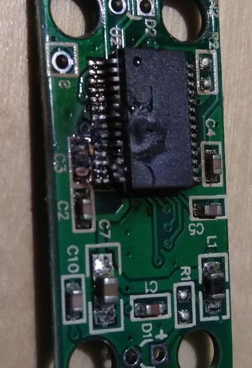
-
hmm looks intact to my untrained eye. I have a 5V 1A transformer kicking around... any chance to power the board independent of the inverter? it looks like all 8 pins of the RJ45 are connected from the transformer board; white,orange,white, blue,white,green,brown,brown. Not sure it will help, but sourcing a replacement isnt going to be easy either.
-
yes you are right of course the transformer is on a smaller board tacked onto the lower black cover panel for the main connection points. It looks identical to your picture Transformer has markings '41-070658-01G RC 2117' but I dont find anything online. 5 pins one side, 4 the other. My little volt meter has a continuity? tester, and I dont see a short from one side to the other. And a least a couple pins on each side beep as though the windings/coils are intact.
-
It was the included cable, hence I bought the adapter, since my attempt interfacing with the BT/BLE was giving garbled results. The inverter was bought as a kit from the nearest national DIY center, the same place that claimed the returned battery had been misused... Not sure how that is possible using their recommended inverter... I'd even set params to limit discharge levels to try and make the batteries last 6 years instead of 4-5... Funny they stopped selling that battery brand the same month. Anyway long story short, they wont be helping with the inverter. F3 looks seems to be 1A, and is very close to the 'PC' RJ45/RS232 port. I notice back-to-back on the board there is a voltage regulator '7805acd2t' and mouser lists that also as 1A. There seems to be a different fuse 'F1' on one of the pins. Which I would have expected to blow first if it was a raspberry pi issue? or you think maybe that voltage regulator could have failed? It is very close to the inverter RJ45 port, so could be related to power Into the board, not out... just guessing... I dont see anything on the board that looks like a transformer. Great tip about the 'King I' thanks. I did wonder about seeing if the display from my new Axpert 11k would work, since it looks identical, apart from the WiFi vs BT change, but I decided that one dead inverter is enough this year.
-
As mentioned elsewhere, this was my previous inverter that had suffered a failed cell on 1 of 2 gel batteries. Whilst trying to diagnose the problem, I bought a USB/Serial adapter and connected it up to a Raspberry Pi. For some reason the USB/Serial adapter failed (partially melted) and blew a fuse in the display board (F3). You know how small those SMD fuses are, and my attempted repair got the display working briefly before it went off again... Is it possible to source a replacement board from somewhere? The board has marking 16-501025-03G along the top. [related to my other thread: I was thinking if I can get this inverter back up and running, then I could test my panel generation capacity using this inverter (and maybe run the firmware update)]
-
I switched the panels into their summer configuration of ~25deg (winter I have them steeper). I hadnt changed them thinking I'd have energy to spare in summer... Anyway I get a slightly better 2.1kW (up from 1.9kW) full sun day. But another cloudy day yesterday was giving brief highs of 2.7kW (and 250V vs 225V). So I decided to try the firmware 57.61. So I followed instructions, opened up the inverter, identified 2809 chip (thanks to great pictures in the thread below, thanks!). I spliced a 1k resistor into the serial cable. Borrowed an old WinXP machine, checked com port (only COM1), and checked the software was running. All good, removed all the house load and solar input just in case, connected the serial cable and started the update... 'UPG YES' appeared, and then the house power shut down... along with the PC and monitor... I guess I needed a laptop Anyway she has been rebooted and is luckily running fine.
-
ah ok thanks! then I have to get it off the wall and check the chip. Just been measuring up for extra panels but I think I actually need a bigger roof top...
-
I climbed up and I am back on single string of 6 panels, she is already much happier. And I understand better now about the 2nd string, and realise I would need a similar number of panels to make that option worth while. Thanks all. I helped my friend with a 60 panel installation last year, and he has also just responded that he is losing generation due to the heat. It should be cooler after today's 40C, so I'll see if she is less sun-shy tomorrow. Anyway I have to delay the firmware until I can find a windows machine and some gloves to use it I suspect the models 'II' and 'I' distinguish the twin vs single, but here they only seem to be marketing the single (maybe dropping the 'I'), and the 'E' is the removable display vs the newer ugly round glowing disco things. I was a bit disappointed when that tiny bar started glowing on mine! Probably that's why the fans have to run all night Maybe I try to find a passive cooled unit once I bricked this one @Coulomb Is there a different firmware file for the removable 'WiFi only' display please? Maybe I can find some strings in there to help with my WiFi utility I started. So far I worked out port 58899 on 192.168.88.n subnet. I see a 'set>server...' message, and can trigger a 'rsp>server=1;' but then I think I got a bit stuck.
-
PS I found a RJ45/serial cable in the inverter box, is that the right one, or is it something special for the firmware updates that needs the resistor. I also previously bought FTDI/FT232RL chipset USB/Serial connector for trying to interface to the old VM III 3kW inverter from a Raspberry Pi after the battery failure, but that is another story spoiler: the adapter melted!
-
sounds fun hehe, and on a hackintosh right btw do you happen to have a pdf of the manual please, the included paper one is too tiny for my old eyes. Model is 'MAX E 11K' (not the twin AC one). I also spotted a technical manual during my search, but again it was for a slightly different model. There seem to be around 3 or 4 variants of the 11K... Since I cant update the firmware today, I think I'll try and grab a couple of these discount panels this month and see what difference they make. Thank you all so much for your help and insights.
-
@Solar RO Thanks, posted at the same time. I dont have a windows installation here, I did notice .pdf instructions in the older zip file that mentioned serial ports, cables and windows
-
@Solar RO Ah interesting, had you also had similar issues that triggered your update or other reason to do so? Do you also find the inverter a tad noisy?
-
Looking in the 57.61 archive I can see a 'dsp.hex' file, the readme.txt seems illegible... The inverter manual mentions being able to do this from a USB stick (3s button press), but does not include instructions, is it just a case of copy file to FAT32 formatted USB stick and pray... (I dont have a windows machine to run included .exe files.) Or is the USB update approach documented please? I seem to recall doing something on another device and having to create a binary compatible file first...
-
Thanks @Proff72 The first half of this year has been great, but unseasonably cloudy... I wish I had graphs for it all! Anyway today is solid blue sky, and it just briefly jumped to 125V (both strings giving my projected max of 250V), but almost like it panics at the amount of power available and winds itself back down to 113V...
