rowesley
Members
-
Joined
-
Last visited
Everything posted by rowesley
-
The RS232 has a separate isolated power supply on this inverter. Just open it and look inside. Yes, you can use RS232 for anything you want as long the EIA232 standard is not violated. To check the power capability of the supply from the RS232 board, proceed as follows: without load, the output voltage should be somewhere between 12.5 and 13.5V, in one of the previous posts I mentioned the exact value in my units. connect a variable resistive load (start with 100 ohm or so) and slowly decrease the resistor value, measure the current and voltage in the same time, until the output voltage drops between 11.5V and 12V, product between the measured current and measured voltage is the output supply delivered power. As I remember,the SMPS transformer size looks enough big for 5W but you have to check if indeed can supply 0.4A without heating the switching transistor.
-
"So if your BMS failed but MOSFETs are still open" what that exactly means? BMS protection should work with or without communication, through a hardware loop. If the voltage exceed the cell max value or if the cell voltage is below the discharge limit, the corresponding MOSFET group (charge or discharge) must be OFF. If in your BMS that is not happening, you have a defective or bad designed BMS. If discharging MOSFET group is OFF and your BMS is hibernating, then you have to wake it up first. AFIK wakeup can be done by initiate a communication or by starting a charge or a discharge sequence. BMS bluetooth is also OFF during hibernation, so without any communication between BMS and battery, once the inverter is loading the BMS, the BMS it should start. Unfortunately on Vevor I do not have LiFePo4 pack, so you are the leader here. Cool for other MODBUS registers findings!
-
You should know that you can keep the PV+microinverters circuit unmodified and to charge/discharge a Li-Ion battery from the existent circuit in an OFF grid fashion. The microinverter AC output need to synchronize to the frequency of a provider grid. If the provider grid fail, you can not use the PV energy even it is full sun. This is the stupidity of all prosumers systems. The workaround for this is (free advice, but with carefully documentation read prior to buy anything): a. connect the AC output of microinverters to the AC input of hybrid solar inverter ( the suggested Anenji), beware to have compatible voltage levels. b. connect to the same AC input of the hybrid solar inverter a small AC sinusoidal output, 50Hz, UPS. The UPS power should be minimum 100VA. This is only for the microinverters synchronization, it should be a proffessional UPS with frequency stabilization. c. connect the hybrid inverter battery input-output to your 24kw Li-Ion battery, 48V is must at this power, beware that you will be able to use only 12kw for a 50% DoD (deep of discharge), meaning around 8-10 years of use. d. do not connect anything to the PV input of the hybrid inverter or connect other PV string that the one you actually have The above solution might work or not, it depends on the specification of your microinverters.
-
Ericson, the French, If you already have microinverters connected to each PV (photovoltaic pannel) why do you want to install a hybrid solar inverter? This conversion method (PV to AC direct) is better than using a hybrid inverter. However, if you want to switch from microinverter to a hybrid inverter just to connect a battery, then definitely I will not buy Vevor. You need an inverter which should be suitable for HV string (12x40V=480V at limit). Most low cost inverters have 500V maximum PV input. So perhaps you can go with 10 or 11 series connected PVs. One good inverter is Anenji 6.2Kw/48V at 500V input. https://anenji.com/products/6200w-48v-hybrid-solar-inverter-on-grid-off-grid-with-wifi
-
Hi Horse, the inverter should work and no need for an external charger. Are you completely off-grid or do you have also some AC input from a provider just to test? The AC input should be somewhere in the range of 170V-250V ac 50Hz. The generator output should be also standardized 230Vac 50Hz. You have to measure at least the generator output voltage with an AC voltmeter prior to connect it to the inverter. Also the ON power button below the inverter case should be turned on.
-
OK, for 5W in minus the quiet is more interesting. However, if you want to get off the error 14, you have to trick the inverter motherboard. This is easy: use a CMOS type 555 as square wave oscillator and set the output frequency above the limit of displaying the error 14. Connect the oscillator output instead of fan RPM output. This will not turn off the inverter anymore if fan becomes defective.
-
I do understand now. 😉 So which is your new consumption overnight with newer fans with error 14?
-
I do not get it: (i)you have a brand new inverter and you have error 14, or (ii) the inverter worked ok for a while, then error 14 occur? Those two situations may have two different approaches.
-
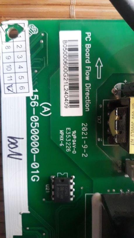
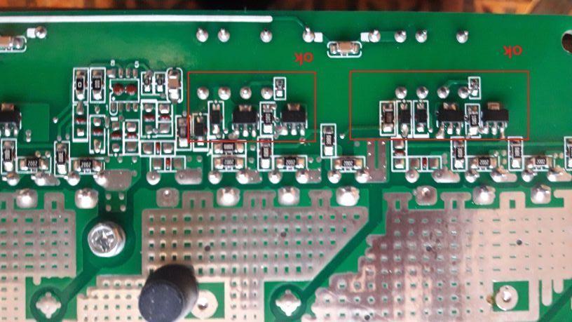
Ok, perhaps someone knows this board (year of manufacture 2021). I have attached pictures with SN, one direction predriver & driver. Any schematic of power section for Easun SML II available somewhere ? I do not know why uploading correct images they are turned. Thx.


-
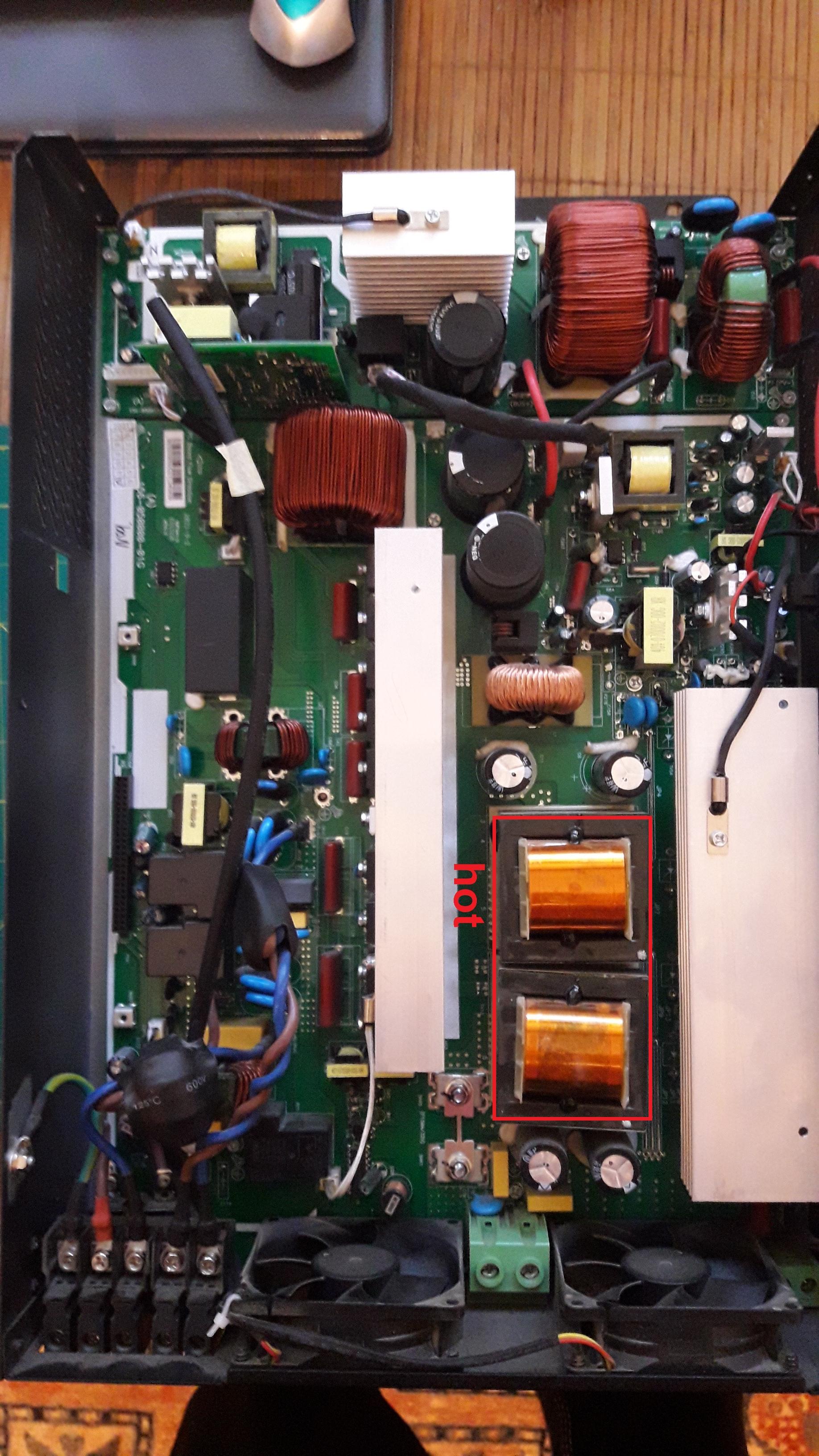
Hello, Any *very* experienced repairing man of isolar SMLII 3.5kw 24V here? I have a unit which works. But, it draws too much power from MPPT to charge battery. It drawn about 70W from MPPT which goes nowhere except perhaps in some heat. MPPT circuit is entirely ok. Battery charger power transistors, drivers and pre-drivers are all good. However both charger transformers have quite high temperature (around 40C-50C) even when the battery charging current is small (below 5A). I do not remember how it was the transformers temperature when the unit was new. A short circuit occur between one PV string wire and protective ground. Before this incident I saw around 2300W from the PV string. After the incident, the maximum MPPT input power in the same solar conditions was around 1400W. The PVs are ok, I have replaced the inverter with a 5.5kw one and have up to 2300w input. Attached picture with the board. Thx.

-
Perhaps: a) check if indeed A and B are tied together in the connector, b) use a slave MODBUS software on PC, and an RS485/USB converter. See what is sending the inverter using a PC software like https://www.modbustools.com/modbus_slave.html A BMS protocol configuration implemented in some inverters is described here: https://workdrive.zohopublic.com.cn/file/vrz5k03066cc0152f4740b9bfff16dd8afe47 or, do nothing and let BMS to do it's job. 🙃Easun SMGII, Anenji and Sumry/Vevor are producing similar devices. I have seen that on 6200/5500 motherboards. Perhaps it is a Voltronic OEM project sold to many Chinese companies for production. I do not think this firmware of EML3500-24L has synchro, however if you find some consistent documentation please post. Indeed you may process 1500W on PV input, I have tested that daily with a tracker. 🙂Your creativity is good. 😉 Yes you may have redundancy for short time. If both inverters are 3500W, inverter A is supplying inverter B. Inverter B fails because the power is 3500W, inverter A will fails as well since the power through it remains 3500W...You will drawn energy from battery by two inverters, one of them just bypassing. Not very economical... To increase your output power without external grid you need an on-grid and off-grid inverter, lets name it Daxtromn (there are other models as well). Use Vevor as offgrid inverter as normal use. Use the Daxtromn inverter programmed as on-grid and synchronized with Vevor inverter output. Both inverters supplied from the same battery. The output power will be Vevor+Daxtromn. If Vevor will fail, Daxtromn will fail as well without any external automation. The second option is to search carefully inside your inverter if the synchronization connector (or footprint of the connector) does not exist even it is not connected outside. This type of inverter seems to be a 2023 design. Most of the offgrid inverters have the on-grid/off-grid option. Actually, this feature must be a routine in the processor which search for the zero-cross of the sinusoidal output and gives a sinchronization output pulse, while is waiting for an input pulse. If the input pulse does not exists, the inverter is off-grid.No, you can't. The output power of each inverter is limited to 3500w. Assuming you have two Vevor inverters and one battery, you can connect them at the same battery, but you have to split your loads in two completely separated branches. In that way you will have 2x3500W loads. The accumulator must have around 14kw to be discharged at max 50%. Useful will be a discharge down to 80% (10-12 years lifetime for Pb-carbon)Fhocorp: "The very boring thing is that the auto-start of the the MPPT part of the inverter that is not working. Every day, i have to manualy power on the inverter (via it's power button) for charging the batteries. For the PV charger to work, the 230V output of the inverter must be switched on, otherwise the device remains completely switched off. The frustrating thing is that if you switch it on manually in the morning and then switch it off again, the PV charger stays on until the end of the day." If so, this is a design mistake. However, the offgrid solar inverter is designed to have inverter ON all the time, so the mistake has an excuse. I've correct a similar issue in two different ways, for both you need to solder two wires on the ON switch and control it from outside the inverter (meaning you turn the switch off forever). 1. use a 5w solar panel and drive a relay (preferable a DC current relay) to turn on-off the inverter (will work only if you do not need inverter when is cloudy) 2. use a 230V AC digital timer (it has 24Vdc internal supply, so you can supply it from inverter baterries) and program it ON in the morning and OFF in the evening, it had the disadvantage that you need to change programmed hours from time to time. I've used a modified method 1 to control the charging current of my my DiY powerwall which is an independent device ( LiFePo4, BMS and inverter onboard). After two years I can say it works good, the AC charging current (from the solar inverter) it's proportional with the sun light.Fhocorp, with Vevor EML3500-24L you can not do that. These types of inverters can not be synchronized. A three phase system has 120 degree phase shift between voltages and variable phase shift between current phases (depending on inductive or resistive load). Your schematic above has one neutral and two phases with unknown and variable phase shift between them. First read about the three phase system and understand it: https://en.wikipedia.org/wiki/Three-phase_electric_power To build your schematic to be useful (using a load which require two or three phases ) you need an inverter suitable for synchronization. What you may get with this schematic it's a split power network for two load sections. On EML3500-24L neutral output can be connected to earth ground as well if you do not have mounted any differential electromagnetic fuses in your installation.Coloumb, this is not the case of Vevor MPPT. The low cost hybrid solar inverters have a simple buck or boost topology for MPPT depending of internal BUS required voltage value. If internal BUS is higher than PV (usually max 500V PV input devices, around 250V-300V nominat PV input), then is BOOST. Easun has the same topology. Voltronic price is twice to third time higher compared with Sumry (Vevor) so it might have tricky things. I did not reversed engineered the Vevor MPPT schematic, but I did for Easun. Vevor is the same by simple measurements ( paralell connected trasistors) For Fhocorp: MPPT means a PWM (puls width modulation) of which the duty cycle depends on product between U and I from PV. So, in a low cost MPPT you will have one or two MOSFETs connected in parallel , one big coil and a number of diodes in anti-parallel between drain and source of these transistors. When there is a lot of energy on the PV, the ON conduction time will be high while the OFF blocking time will be low. The processor will try to keep the input power near the ideal UI curve of the PV by measuring U and I and controlling accordingly the ON-OFF time of PWM. Vevor MPPT is following very well the input UI curve for low PV energy input (small ON conduction time). Of course, when it works. 😂BTW, there is no MPPT bridge. Just two MOSFETS connected in parallel and three double switching diode...@rowesley , did you encounter any difficulties when unsoldering the MPPT power bridge? No because I have around 40 years of hardware experience. Use good solder wire (60%tin-40%lead) and mix the lead on the board with it first. Use a solder iron of about 60w, then use a good tin pump. 60w electric tin pump is good as well, bit solder will be spread all over around...😂 The "lead free" chinese boards have a poor solder...maybe is not 60%lead but is definitely somehing else than tin. You have to replace that PV input capacitor with a 6000h or 10.000h one (10-15 euro pcs). Use 200V one or even higher value. You have also to check Q6, Q8 transistors from the heatsink I've take photos and the output of U10 driver. One of the transistors may have short circuit between drain and source. But you have to replace both with the same type. Take a magnified view of the picture posted and see the replacement type, there are already mounted on heatsink. You should also check two parallel capacitors of 680uF/35V, I do not remeber those part numbers. Good luck.Fhocorp, this is my third email trying to answer, there is a problem with this forum. Both MPPT and DC charger heatsinks need termal grease. 6xTO220 transistors on charger side with simple heatsink removal no desoldering need, 2xTO247 transistors on MPPT which need desoldering for 5 devices as pointed in a picture above. The MPPT should be supply below 150V. If not, the MPPT transistors will crash even with small load. The battery voltage is available on the MPPT input on this model. You will get no service what so ever from any Chinese company. Vevor is opening tichets, after a long debate, requiring pictures, movies, etc, they will send directly from China a replacement board, which of course does not fit for your inverter. If you have 3500W inverter they will send you 5500W power board, or a 3500W power board suitable for other model. If you will complain about that they probably will say to send it back to China and wait for a replacement. What I'm saying is based on my experience with Vevor. However, this inverter is much-much better than Easun models which btw draws 30W form battery and 30W from AC ( no matter it is sun or not). Also the Easun 3500W model with 6000W MPPT is consuming 200W on bypass mode. Do not touch fans control, they need to blow.😂Vevor EML3500-24L does not have factory default any thermal grease between the MPPT power transistors and heatsink. Transistor drains are electrically connected with the heatsink . This is killing at least one transistor very quickly. The picture attached shows the transistors which need thermal grease, the TO247 parts on the edges.
 Yep, you have right. USB isolator then.Read previous posts, it works for me."Not in my experience. All the Axperts I've looked at common the digital ground with generated AC-out neutral. That should be at roughly ground potential, but may not. " Coulomb, for inverters having AC neutral not connected to the Earth neutral, you can connect it outside. To avoid damages, use a 25W Edison bulb in between AC output and Earth ground, if the filament stays cold ( no current flow) replace the bulb with a wire. Once your digital ground is connected to the Earth ground, the computer ( which has his ground connected to Earth ground through the supply cable) is safe. Laptop is safe as well since the adapter SMPS is isolated and it's ground is internally connected to Earth ground with a HV capacitor. Experience is a mater of age. You know more near the retirement, when anyway it does not matter what you know...nobody care🤪