


bobah1248
Members
-
Joined
-
Last visited
Everything posted by bobah1248
-
@kuba.cz Thank you very much! What you wrote coincides with my observations (plus or minus the measurement error of the inverter itself) My inverter says that the ZZ parameter is 01, i.e. Germany. In other words, this is already the lowest possible level 😥
-
I'm glad I got the point across. 😄
-
This can be checked in simpler and less dangerous ways. For example, measure the voltage using AC voltmeter between the L terminals of the inverter input and output (then between N terminals) - if it is about a couple of volts or lower, then the bypass relay is closed. Another way is to switch parameter 03 ("AC input voltage range") from APL mode (90-280VAC) to UPS mode (170-280VAC), then wait until the voltage in the network drops below 170V (this happens to me on one phase every day) and look at the bypass icons, input and output voltage, you can measure with a voltmeter as in the previous case. Any way, I checked both of them and can say - if bypass icon present on inverters display, the grid relay and load relay are closed. Uploading Attachment...
-
@Youda In my inverter selial interface command QPIGS (Device general status parameters) has valid parameters: Y Solar feed to grid status (reserved feature) 0: normal 1: solar feed to grid ZZ Set country customized regulation (reserved feature) 00: India 01: Germany 02: South America AAAA Solar feed to grid power (reserved feature) A is an Integer ranging from 0 to 9. The units is W. I believe that it is under the ZZ group that all the settings for exporting to the power grid are hidden
-
I am 90% sure that it is shorted for the following reasons: the output voltage is equal to the input voltage to the inverter the screen shows the "bypass" icon The only difference is that the inverter pumps in as much solar energy as the household consumers need (according to its output ammeter). At the same time, the input ammeter shows fractions of an ampere, which means no export (and import, if there is enough solar energy) In any case, forcing the relay to close is a very bad idea: it explodes IGBT transistors, burns IGBT drivers and even control transformers inside the inverter ☹️
-
I agree. When my inverters burned out, I thought a couple of times how I could implement the inverter control program myself. But it seemed like a colossal amount of work that would take about six months. In any case, before trying to cheat the firmware, I turned to this forum to understand what consequences could await me, in addition to understated readings and generation of undervoltage when working without a grid (according to my calculations, when setting 220V, the inverter in offline mode will produce almost 209V; and this is just the tip of the iceberg that i can see now). I also thought that instead of constantly overvolting, I could temporarily connect resistors. This is like a kickstarter for hysteresis - inverters turn off export when the voltage is below 175V, and turn on again when the voltage is above 195V or so. This would allow me to restore export when the voltage temporarily dropped below 175V, but then returned to 185V. And because of hysteresis, export does not resume. Thus, I could push the inverter to resume export, fooling not the entire inverter, but only a part of it and for a very short time (connect a "patch" resistors for a few seconds)
-
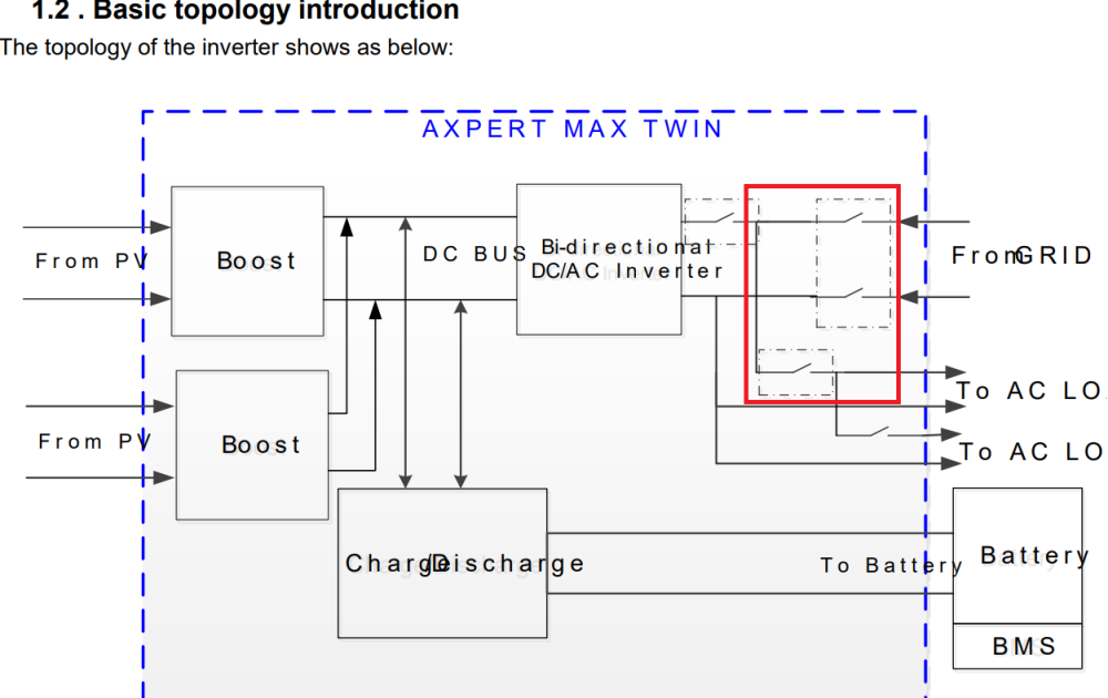
@Youda Yes, this service manual is aplicable But my inverter is missing several minor modules: SCR Board PV EMI Board REMOTE & WIFI Board AC breaker The inverter's appearance and controls look 100% the same. The "1.2. Basic topology introduction" diagram, cross wiring PCBs, fault and warning codes are same.
-
Thanks a lot - I have the same vision for AC input and output, as well as HVBUS does not affect when the AC output voltage is lower than the HVBUS Yes, I have seen threads on this forum where this was worked out in great detail and appropriate conclusions were made. Anyway, thank you very much for mentioning this point. I agree with you 100%. This is exactly what I tell my friends who complain about the energy supply company, but at the same time do not want to limit their electricity consumption to improve the situation ☹️ This has already been done - I am literally 15 meters from the grid transformer, I laid short but thick cables to the power grid, I distributed the export so as to somehow balance the voltage on the phases of the power grid. But the power of the power grid transformer does not correspond to the all-season load. It would be better not to torture my inverters, but to wait until the grid transformer burns out and the power supply company replaces it with a more powerful one 😈😈😈
-
@Coulomb Thank you very much for your feedback. In fact, I was only worried about one thing: let's say I change the voltage measurement characteristics at the AC input to +10V. Then I turn on the export, the inverter will close the bypass. And then the inverter will see that at the AC input, say, 190V (real 180V + 10V my virtual bonus), and the inverter AC output sees the real 180V. If I were the inverter, I would be confused, then decide that the inverter is faulty and refuse to work. The same applies to the internal high-voltage HVBUS bus, from which the "sine wave drawing" occurs, as well as battery charging/disharging. That is, I think it may not be enough to simply change the resistors at the AC input - I also will have to change resistors at the AC output, then possibly on HVBUS, and this in turn will require redoing the same on the MPPT sensors and possibly even the battery charger. In principle, it was this chain of probable events that made me write my question on this forum. It is possible that I am simply exaggerating and the firmware in my inverter does not care about the listed inconsistencies. But, since you have never encountered anything like this, I will have to be extremely careful if I decide to do such a rework sometime in the future. Thanks a lot!
-
@Beat Unfortunately, my percentage calculations are correct. Although the accuracy of measuring the electrical characteristics of inverters leaves much to be desired, the inverter shows exactly 80% efficiency when reading data via the serial interface. I also correctly calculated 20% from 6 kW (from the input power), and not from the 4.8 kW (where the efficiency has already been recalculated). Regarding the declared efficiency of inverters by the manufacturer, you most likely saw the "Peak Efficienty" parameter. That's right - in ideal conditions (for my inverter, air temperature 20-25'C, humidity 30-80%, voltage at the MPPT input 380VDC, resistive load that not more than 80% of maximal power inverter), inverters are really capable of delivering an efficiency of up to 93% and may be even for several minutes. But as soon as the voltage on the MPPT drops, the temperature on the transistors and inductors rises, and the efficiency begins to fall rapidly. And at this point, you need to focus on the "Rated Efficienty" parameter, which is not declared by all manufacturers (too many dependencies, even the region of usage affects the efficiency) In any case, "Rated Efficienty" usually does not fall below 75% (again, in ideal conditions for air) and this is taking into account the full chain of DC-AC conversion. Anyway, thanks for your thoughts and calculations.
-
@HennieL Thank you very much for the link. As I wrote above, I installed a powerful industrial fan that ventilates the air well (sucks in from outside the house). Since my inverters have radiators inside, I additionally installed a computer fan on the problem inverter so that it would forcibly remove air from the inside. And yes, it works, but for now the outside air temperature is below 35'C. But now the outside air temperature in the shade is on average 42'C and this continues every year for about 60 days. I think I just need to put up with these abnormal two months (the first one already left) and not overheat the inverters because of electricity export. Especially since the components for repairing inverters are very expensive (and if the electrolytic capacitors will dry out due to the overheating, then they will have to be ordered from China or Russia, and wait for delivery for about a month)
-
@HennieL Thank you for suggestions. Regarding the direction of the blowing of the built-in fans - I have installed separators inside the case for now and broken the closed loop, additionally installed a computer fan to blow air out of the inverter from the top. But, as it turned out, computer fans are too weak - their power is less than 200 mA (at 12 V). I found more powerful fans of a suitable size on Aliexpress, with a power of 1-2 A (at 12 V). And bought one to try, but it turned out that they have a power of only 0.8 A (at 12 V), although according to the anemometer, the air flow is about 1.5 times more powerful than the computer one. In general, I see 3 options at once - either liquid cooling, or make holes in the inverter and add dust protection and additional fans, or buy the right inverters ;) Regarding the Peltier elements - I have them and I even tried to play with them (air and liquid cooling). But their value is, to put it mildly, exaggerated. Let's do some calculations: I measured the efficiency of the inverters, and it is about 75-80%, which is not bad in general Each inverter in hot weather can receive about 6 kW from solar panels, and give out 4.8 kW to the grid (at 80% efficiency) Thus, each inverter converts 6 kW minus 4.8 kW is 1.2 kW of energy into heat. Moreover, these 1.2 kW have 100% efficiency I have 2 inverters, which means I have a powerful electric grill with a total power of 2.4 kW 😂😂😂 Each Peltier element consumes about 1.5 A, which means its power is only about 18 W Thus, to remove 2.4 kW of heat, we need to spend about the same power Then 2.4 kW divided by 18 W, we get that we need at least 133 Peltier elements, provided that they are 100% efficient, which is not the case (or at least 66 for each inverter) It is simply impossible to install so many elements directly into each inverter 🥲 But, of course, the idea was good - it is similar to idea @Beat installing an air conditioner, which will try to spend about 3 kW of electricity to get rid of 2.4 kW of heat. It is for this reason that I had an idea about heating water for household needs - i.e. I would spend these free 2.4 kWh of heat on what I am already forced to spend every day 😀
-
@Youda Thank you very much for your detailed answer! Offtop: To be honest, I chose inverters from what was on our market. In the process of choosing, it turned out that our local sellers simply resell what is illegally imported from China. Unfortunately, we still do not have dealerships or service centers that could give an answer at least somewhat similar to yours. For example, I had to assemble a cable for connecting the BMS to the inverter myself, as well as make settings for the BMS and inverters. In general. I think you now have an idea of the level of local sellers. As a result, I chose between Voltronic and Deya, without the opportunity to see and compare their work in any showroom. In the end, I managed to find a way to buy 2 inverters and a battery directly from China. However, I was only able to find copies of Voltronic at a reasonable price (but I found out later that they were copies). Let's get back to your recommendations: my inverters are budget ones and they seem to have everything (including export), but this is mostly added "just in case", and not for the intended use (in principle, I discovered this myself after purchasing them) it turns out that judging by your picture, the best hybrid inverter looks like the inverters from Deya due to the possibility of flexible settings and responsive service I need to cool the inverters forcibly with a large volume of air - this is exactly how I have it now: in the room there are only protective grilles that do not allow it to heat up from sun, an industrial fan of more than 200 W is installed. To make the cooling even better - this is only removing the front protective panel of the inverters, allowing the industrial fan to blow directly on the radiators, transformers and inductors. But this creates the danger of large amounts of dust and conductive particles getting into it regarding liquid cooling - everything is exactly as you said: I live in a private house, I have storage tanks for hot water. In addition, water is relatively cheap here, and I can heat the pool or simply turn it into fog (using a microclimate system) - it is very hot here in the summer, low humidity and a lot of dust therefore, liquid cooling would allow to reduce the temperature on the radiators by approximately 2 times, compared to air (+40'C air temperature will be worse than +15'C water temperature) as an option, for cooling, you can assemble a heat pump that would not use liquid, it would allow you to safely heat the water in the storage to 70'C, while cooling the radiators to 35-50'C, but this is a completely different story and research I completely agree - properly designed and assembled equipment is a guarantee of safety for both the equipment and the home, including its residents. Therefore, thoughtless conversion of radiators to liquid is not acceptable (for example, to computer, which successfully works with equipment worth several thousand USD). And first of all, because the solar power plant works not only with high voltage, but also completely autonomously (without direct supervision of people, as is done with a PC) I had to repair inverters and in the process, I discovered that the cooling in the my inverters is assembled a little strangely: one fan (MPPT) blows from the bottom into the inverter and the other two (220VAC and Battery) blow the opposite way - from the inside to down i.e. in fact, the air inside my inverters is looped!!! I added several fans, which slightly improved the overall situation, but it worked well while the air temperature was no more than +35'C If you are interested, here is the story of my inverters and the overly high voltage of 6 kV
-
Central Asia, Uzbekistan Yesterday the air temperature was +46'C 😅 And today it was cool +40'C 😉
-
@Bobster. The basic behavior of the inverters is 100% consistent with the paper user manual. Export to the power grid is very similar to the USb mode (see 01 Output source priority) - in this mode, the inverter operates in bypass mode, but adds to this grid voltage as much current from the panels as is required in the load. Thus, the voltage in the house is equal to the voltage in the power grid. There is another parameter "03 AC input voltage range", which forces to completely disconnect from the power grid and switch to the inverter with an exact voltage value of 220V (or 230V, as in your case). That is, if I set the UPS mode, then disconnection from the power grid will occur if there is less than 170V. But if set it to APL and then the inverter will continue to maintain the connection even down to 90V. When the export mode is enabled, the inverter stops limiting the current consumption and it begins to flow into the grid through this open bypass. From this point of view, it seems strange why the export stops at 170V, although parameter 03 still allows supplying down to 90V to the house and, moreover, the admixture from solar panels occurs normally. I.e. the limitation on the admixture of solar energy is simply re-enabled (I can clearly see this in the status when requesting QFLAG and QPIGS from the inverter via com-port). This point surprises me very much, and if my vision of the inverter operation in export mode is correct, then I am inclined to think that there must be firmware or an inverter for which the limitation is not restored to a fixed value of approximately 185V-170V. In addition, I have the impression that this threshold is adjustable and is stored in the EEPROM chip. And, with due skills, this value can be adjusted directly in the EEPROM chip or by command via the serial interface (possibly the display serial interface, but not the one that comes out on the connector on the front of panel)
-
@Demo I'm not sure that the problem is that the inverter is a clone. I'm 99% sure that the main firmware is not the same as the original. And I'm interested in whether there is a problem with export in other inverters (including original ones). The answer to this question could rather be given by someone who is familiar with the firmware from the inside, like @Coulomb
-
Thanks a lot for the recommendations. @Beat I asked for cheap solutions 😉, while installing additional air con is not cheap, as well as stop exporting - export gives me an extra 100-150 USD per month (or about 2% of total cost of solar station). It's a pretty good return on investment 😀 @GreenFields Unfortunately, my inverters are not able to export energy from batteries. In addition, this will increase the wear of the batteries, which will not be covered by the cost of grid electricity in any way. I have plans to install water liqiud cooling for inverters - this should not only be cheaper during modernization, but will also allow me to save on hot water for household needs. Yes, in my area there is no centralized supply of hot water, so heating water and accumulating it could make sense. And this is one of the reasons why throttling worries me less than export stability.
-
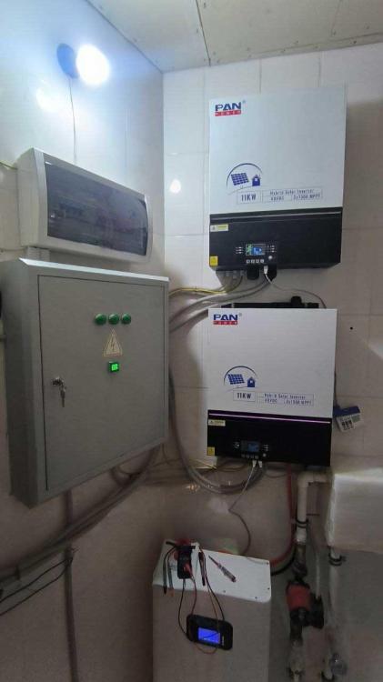
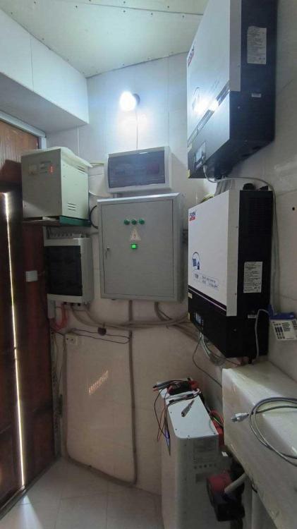
Hello everyone! I live in a region where it is very hot in summer, and the infrastructure still leaves much to be desired. To solve the problems with the lack of electricity, I installed a solar power station. But I assembled it with a reserve (about 3 times more than my needs) for cloudy or short winter days. I also planned to export the surplus to the grid. For about a month now I have been struggling with: too hot air around the inverters (the outside air temperature is over 40'C) Because of this, both inverters overheat (the temperature of its sensors reaches 70-75'C) and, as expected, begin to throttle. One inverter produces approximately 80% compared to the time when the air temperature was below 30'C. And the second, on average, produces only 50% of what the first inverter produces at the same time. And this behavior was from the factory / the moment the inverters were installed. Another problem is that the voltage in the power grid is very low (about 180V with a standard of 220V) Three phases come to my house, and such low voltage during the day on all three phases (not evenly, but with an imbalance between the phases 180V - 190V - 160V). When the voltage drops to about 185V, other inverters stop exporting. But the mixing of solar energy into the house continues, as expected (this can be seen from the meters before and after the inverters). At night, the voltage rises to 210V and, as expected, in the morning the inverters cheerfully begin exporting. Until the voltage on the corresponding phase again drops below 185V. And it does not resume until it rises above 200V (i.e. until night). Problem #1 with incorrect throttling of the second inverter would be something that would be nice to solve, but problem #2 looks even sadder in comparison. What I have done so far: solar panel power: 4 strings of 7 panels with a power of 550 W each (i.e. each string is 3850 W at peak) in 2 identical inverters with a power of 11 kW and two MPPT inputs of 5 kW (where each MPPT receives 3.8 kW maximum) clone of Voltronic MAX E 11K replaced the power grid cables with more powerful ones and checked them with a thermal imager - the cables do not heat up compared to the surrounding air I previously connected a voltage stabilizer before and after inverter, but it ended sadly and I had to repair the inverter (after repairing it works perfectly - throttles 80%) In other words: inverters are loaded only at 77% of their maximum capacity they are balanced across solar panels and distributed across different phases of the power grid losses between inverters and the power grid are minimized the inverters and electricity meters themselves are logged into Home Assistant and are monitored (in parallel with billing of the energy supply organization) Now the question itself: I can't tell the inverter to export to the grid, even at low grid voltage (i.e. this behavior does not depend on the "03 AC input voltage range APL\UPS" parameter). Adding a voltage stabilizer kills the inverter. I have not seen any firmware for my inverter on the Internet that would fix the described problems. But, I can open the inverter and "patch" its AC voltage sensors so that it thinks that the mains voltage is still normal - say, so that it sees 180V as 190V. Does anyone have any thoughts on these unplanned inverter circuit changes? Pros, cons? Or does anyone have any cheap but smart ideas?
-
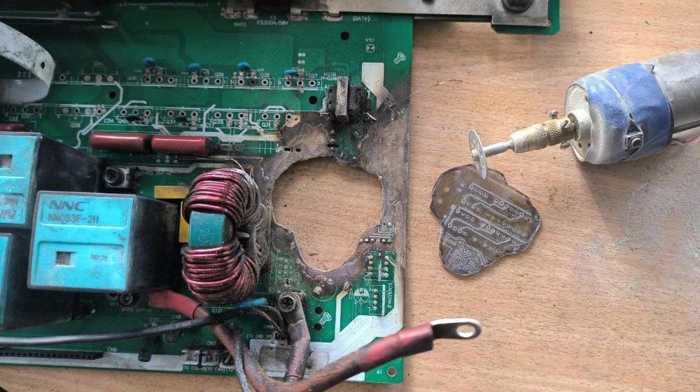
This is what the result looks like. I would like to supplement the instructions of @BritishRacingGreen with a list of steps for diagnosing and repairing the inverter parts that I had to repair and that he did not touch.
-
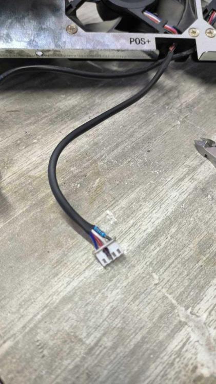
The final chord was that these inverters have smart fans. I bought one in early January in an online store at a very high price. Unfortunately, its delivery was delayed and I still have not received it. In addition, it turned out that: - the power of the ordered fan is lower than those installed in the inverters - 3 such fans completely burned out in two inverters Fortunately, I managed to get around the problems to some extent: 1. In one fan, the feedback "slightly burned out", due to which the fan was not able to reliably report that it was rotating (it was visible in the system as jammed with error code 01). For it, I added a resistor in the connector so that it would help this contact reach the required levels. This fan was installed in an inverter, where the other 2 were working. 2. From the other two fans, I managed to assemble one. Unfortunately, neither the speed control nor the feedback worked on it. Therefore, I assembled a fan control circuit, depending on the temperature on the sensor. At first, I wanted to assemble a circuit on an operational amplifier/comparator, which would turn the fan on or off. But it was boring and then I decided to install an additional controller that would completely emulate the operation of the fans from the inverter's point of view. Unfortunately, my workload at work would not allow me to spend enough time on this. And then it dawned on me - I can use a DC-DC converter, which will be controlled by NTC. No sooner said than done, and now I have 3 of these modified DC-DCs installed in the inverter, controlling 2 native and 2 additional fans. I made the following settings: - smooth regulation of rotation speed (cooling flow and noise volume) - at a temperature of 25'C, the fans have 5V, which corresponds to 20% of its speed - at a temperature of 45'C, the fan has all 12V, which corresponds to 100% With such settings, the inverter with such coolers is about 10'C colder than the one with the factory fan configuration. And some photos


-
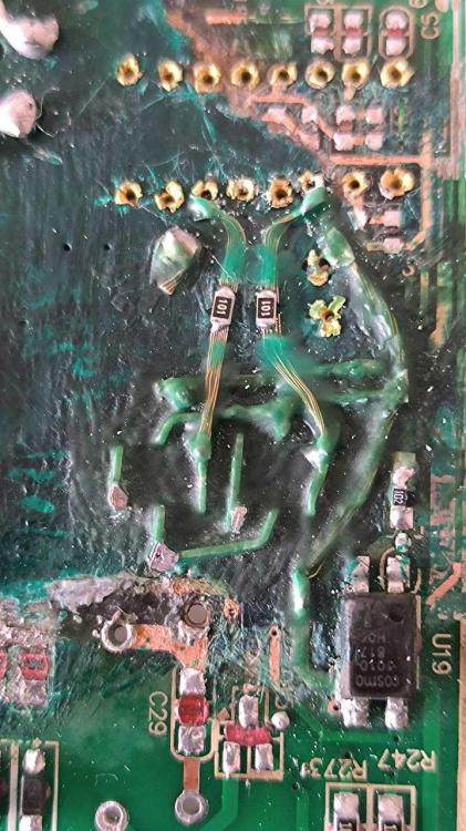
I apologize for the long silence. As promised, I tried to read the contents of the MCU's flash memory. And as @Coulomb said - it was not easy. Along the way, I had to understand: 1. TI stopped supporting registration on its site of users from my country (Uzbekistan) at some point 2. I tried to log in to the TI website under the account of my previous job (a European company that closed down), but without success 3. Reading from flash is supported by CCS3 (I managed to find a copy of the CD), but it works with a different programmer than the one I have (XDS100v2) 4. My programmer with "dancing with a tambourine" can be screwed to the latest CCS, but I could not find how to read the contents of flash memory 5. Again, C2Prog 2.x works successfully with my programmer. But reading from memory is available through its "gdb client", and via a script in LUA In general, I was able to make sure that flash memory, as well as RAM and ROM are blocked and return only zeros. The exception is the addresses of some peripheral modules. Luckily, I managed to find partially damaged components on the control board. After fixing them, the MCU miraculously started working, controlling all connected peripherals (respond on display controller requests, AC generation, battery charging, MPPT and so). And since my inverters have specific firmware, which most likely no one except me needs, and I managed to start the inverters, I decided not to bother with the firmware anymore.
-
I am a full stack hardware designer (PCB, 3D modeling of cases, firmware, pc software, etc.) with more than 15 years of experience. I think I have enough strength and patience, and under your sensitive guidance, to figure out how to extract the firmware. It took me weeks to convince the seller to send me only the control boards. Unfortunately, their company does not support customers at that level. I will try it soon.
-
@Coulomb Thank you very much for your detailed answer. Both inverters have: 2 independent MPPT 1 AC input 2 AC outputs (main and second wia coufigurable relay) 1 DC battery port firmware supports parallel connection (include 3 phase mode), LiFePO4 batteries 15 and 16 cells and communication with its BMS I attached some crazy pics of the shit I was struggling with 🤪. Hope you enjoy it 😂😂😂


-
Hello everyone! First of all huge thanks @BritishRacingGreen, @Coulomb and @Maxo for the circuits and the helpful guides with steps to revive inverters. I have crawled a long way, getting bumps and bruises. And in the middle of the way I came across this forum and forums.aeva.asn.au. After which I just ran along the beaten path. What do you think might happen if a 6 kV power grid feeder suddenly drops to a 0.4 kV household power grid feeder? You will all be right - nothing good can be expected. I managed to restore almost everything, including the diagnostics and repair of which was not touched upon or described on this forum. But I faced the impossibility of bringing the TMS320F2809 microcontroller back to life on the control board. At first, I did not know what firmware it should have, and so I somehow managed to buy 2 new control boards. Unfortunately, before I found this forum, I successfully burned one board (the main board supplied +12V instead of +5V). Today I managed to fully start one inverter 😆. And as a thank you, I would like to share my experience on this forum. But before that, I want to bring the second inverter back to life by flashing the TMS320F2809 microcontroller with the correct firmware. @Coulomb, can you please help me with flushing firmware to TMS320F2809? The working inverter says these firmware versions: U1 64 03, U2 38 04. I fixed all dead chips (that powered directly from +5VDC). I have TMS320F2809 and TMS320F2808 chips as well XDS100V2 programming tool. So, I need right birary image or hex file with bootloader and main firmware. Or steps to burn those if they in separate files. Not sure if I also should lock JTAG with some password. EDIT: fixed measurement units - kW (kiloWatts) replaced with kV (kiloVolts), so 6 kiloVolt feeder (6000VAC) drops on 0.4kiloVolt feeder (220VAC/380VAC)


