Marcellino1975
Members
-
Joined
-
Last visited
Everything posted by Marcellino1975
-
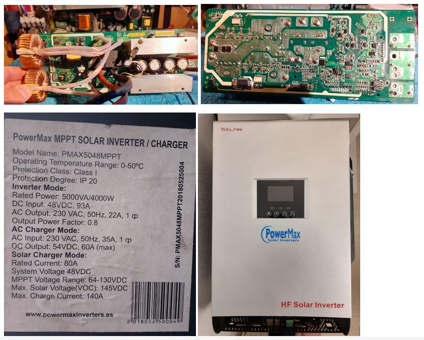
Hi Everyone & Coulomb, Thank you for you replay. The following has been done last week. The repair has been stopped. We have decided to not repair the MPPT (SCC) and leave it as is. The inverter is further working okay now. We going to place an separate Victron MPPT charger (150/35) which will be used for charging directly the battery. The Victron can be adjusted to limit the charge current. Regarding the resistor that was open, on this resistor on the "hot" side the PV voltage could be measured. It was connected through two diodes and an transistor directly to PV+ The other side of this resistor should be high, but was around 0V because an transistor was active (connected to ground) This transistor was activated by one of the outputs of the 74HCT541, also located on the PCB. I think it can be repaired, but I don't have the time to completely reverse engineering the controlling schematics on this board. I did already find the schematic of the power components, but did miss the part of the two automotive relays. It is not my own inverter otherwise I would take the time to draw up the missing part of the schematic, but as said I've unfortunately not the time at the moment.
-
Hello Everyone, I'm Marcellino, living in Spain for an half year now, and helping my neighbor with his defective PowerMax solar inverter. The inverter is used with an LiFePo4 battery. Unfortunately the on /off power switch of the battery is used to force shutdown the inverter. The power switch of the inverter itself was defective so it could not switch ion or off. The configuration settings of the inverter didn't match with the used battery. So the inverter has operated while the battery BMS has intervened several times by disconnecting the battery due too high recharging rate of the battery. This caused error 08 to be reported, an also a BUS voltage too high message. I've configured the settings to match with the battery, with also a limited charge current for the attached battery. This is now working correctly; when connected to mains the battery will charge with the maximum set current, without the battery BMS getting activated. Off grid operation is also working, generating the set 230 Vac without problems. Now the issue; it won't start charging through the SCC. Only the battery and PV is connected to the inverter. PV is simulated with an stand-alone power supply (off-grid from my camper van) Range from 60 - 145VDC is all used. Only a small load (fan - 40W) is attached to the inverters AC output. When turning on the PV voltage, and raising the voltage will start the attached FAN on the SCC board for a few seconds. On the inverters display the "solar panel" logo start to go on, and when raising the PV voltage to approx 100VDC also the "sun" logo on the display goes on. The display also shows the correct PV voltage (as connected - provided by the PS). Then I should expect the two big 12V - 70A power relays to switch on (on the SCC board) but this won't happen...the "solar panel"and "sun" logo disappears and the after a few seconds the SCC fan starts to spin again. Then on the inverters display the "solar panel" logo start to go on, "sun" logo appears and PV voltage pop up again, in order to stop again and to repeat.. I've checked all the voltages on the SCC board, and do not miss anything. I've only found a defective SMD (2512?) resistor (R73) of 30K which was open. No visual signs of defectiveness on this part. I've also checked the power components and functionality of the optocouplers (the two for communicating wit the control board) I didn't find any schematic of this board yet, and I'm currently out of options. Already spend a lot of hours on this device and keen to get it operational again. Most of the time it is small component which fails, but how to locate it? I hope that someone can help me further in order to get it working again. I will try to post some pictures of the board as well a video showing the restart behavior of the SCC board. Video : https://linksharing.samsungcloud.com/9ZYcX4QFE8Q8 Thanks, Marcellino