


rs01
Members
-
Joined
-
Last visited
-
-
-
-
-
-
-
-
Thanks for the guidance. Yes actually it is Error 53 = "inverter soft start failed", I will correct that. "four SOT-25" is that the rear of the board near CN11? Do you have the pinout info for CN7, 9, 10 & 11 or any schematics you could guide me to? Any recommendations for removing conformal coating? I have 14 days to wait for a viewing aid from an online store. "SOT-25" are very tiny things to test for me 🧐🙂 Foolishly and naively as I have never used TI CCS before or heard of a "DSP" either, I was hoping to get a JTAG connection to the DSP to debug inputs and outputs using TI CCS if I knew the I/O for CN 7, 9, 10 & 11. other than that i'm stuck waiting for minimum a component viewing aid then the replacement board most likely. No big loss this 5048 was always a weak machine IMHO. Could be you're correct and damage to those ULN2003A NPN outputs or those SOT-25 not activating them? IDK. Lots to learn.
-
-
Thanks for the guidance, I'm obviously out of my experience on this but will continue trying while waiting for a replacement board. good suggestion RE the ULN2003A. I'm waiting on a microscope and won't attempt any component changes until I have it as I have no soldering experience at this scale.
-
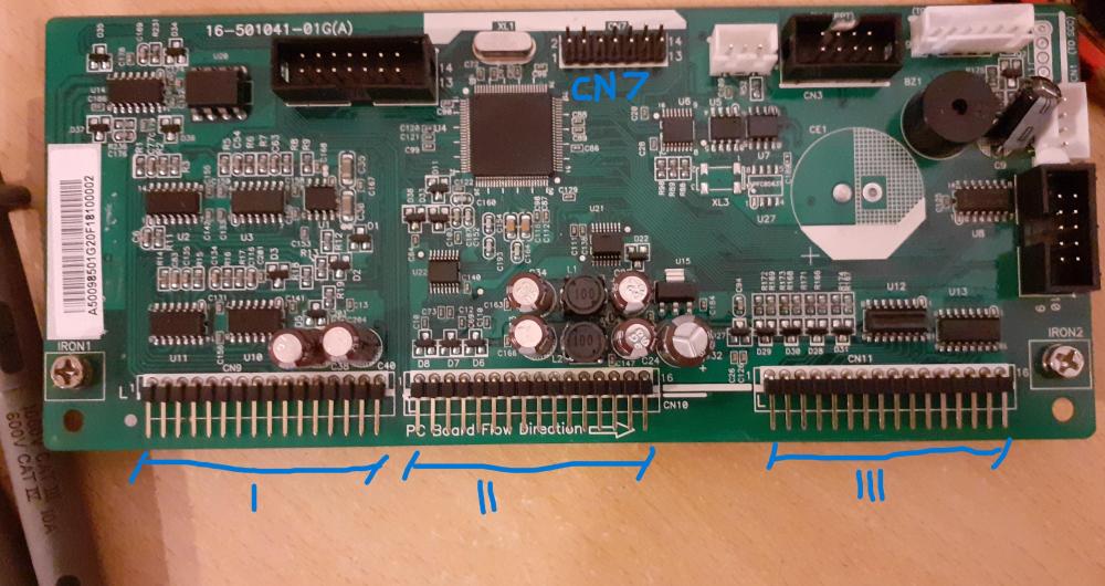
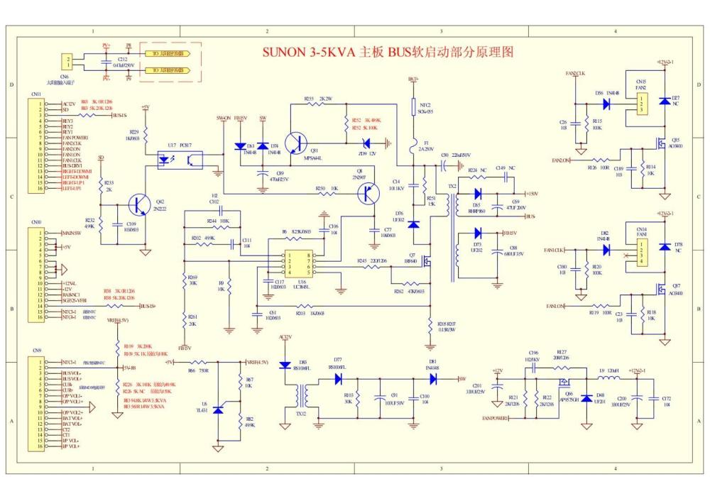
NTF, New To Forum. The purpose of the post is to steer myself towards a repair, which I currently rate as a < 10% chance of success (due to basic tools and experience for SMD / SMT repair). If other NTF get some use from the post all the better. Not yet familiar with the forum layout but found some useful notes RE: Inverter repair so I am attempting to use those notes / posts to repair a PIP-5048MG from MPP Solar that burnt its "main board" near the battery charging circuitry, see pic. Mainboard appeared too damaged to repair. Other posts suggest Solar Charge Controller SCC is unsafe for these models. I had noticed very odd behaviour when Grid charging was enabled using firmware U1= 71.85. After replacing mainboard with a part from MPP Solar the inverter powered up but displayed Error 53 "inverter soft start failed" then shut down. The original system had 2x inverters in parallel. MPP Solar "support" stated Error 53 required another main board replacement. The original system had 2x inverters in parallel. Using a control board from the undamaged inverter Error 53 was no longer present for the replaced mainboard and the inverter worked ok with replacement control board, given this It seems likely that the control board is in this case the cause for this Error 53. Control boards for 5048MG are not easily available from MPP Solar and currently require "special order"... lead time 45 days and they have not agreed to supply firmware to ensure the undamaged inverter can have matched firmware. I will attempt a repair while waiting for a replacement control board. Using a magnifying glass, No obvious damage on control board and it will take upload of a firmware file (link post). The Digital Signal Processor DSP on the control board is a TMS320F2809PZA from Texas Instruments. I don't know what the best steps to diagnose and repair this or any given SMD / SMT circuit would be but in this case I'm attempting the following... Open to guidance. Step 1: Research similar topics on forum, eg. Repair of Axpert Inverters and PIP inverter repair index page, "bus soft start failed" Step 2: Inspect board for visual damage...burnt components, broken tracks etc. Experienced people might create "traces" of the circuit they are inspecting as they go... very time consuming for the inexperienced but do attempt logging / noting major components. Minimum tools required magnifying glass and notebook. Nothing obvious so far! Step 3: Find any available circuit diagrams that are relevant to task e.g. PIP-5048MG control card or "bus soft start schematics". Available Schematics index page would be nice. Step 4: Remove conformal coating on control board where test probe access could be useful... paint thinners is partially successful at this. ---....paused... Step 5: Find most significant "pinout" info, e.g. CN7, 9, 10 & 11. With visual inspection CN7 has connections to DSP communications channels and CN9, 10 & 11 are main connection points to "mainboard"... (IP), using multimeter and continuity test CN7 has JTAG interface (might be useful with TI code composer studio to inspect I/O see link post JTAG), pinouts not confirmed. but so far CN7 looks like TDO = 7, TCK = 9, TMS = 1, TDI = 3, VSS = 4 other pins may be required. Step 6: Ideally here at least would be to get power on the board and connect to DSP to inspect I/O. currently inverter shuts down so might need bench top power supply and CN 9, 10, 11 might be similar to attached schematic.


-
-
Whats an electric geyser? never heard of them. I will look them up. definitely preheating is a good idea along with pipe insulation, passive pays off. Water heating panels is a good idea alright. Water heating panels definitely work very well even way up in the northern hemisphere not great in the winter when days are short and the sun is low. What about a parabolic mirror with solar tracking focussing energy on a heat-exchanger? or something like these https://www.heliotrack.com/Parabolic.html

