Christoff83
Members
-
Joined
-
Last visited
Everything posted by Christoff83
-
Thank you. As much as I'm trying to build something workable for the parents as quickly as I can... this is also a learning experience for me. I've built working POC's now with an 8-pin relay as well as full 63A ATS. I obviously want to make the solution work reliably, safely and fully compliant. It's been quite surprising how many varying (and sometimes contradicting) views there are out there from people in the industry. Anyway, thanks again!
-
Awesome thanks, I didn't realise that. And you're comfortable using such a relay for a system connected to your home's DB instead of a more off-the-shelf ATS? Thanks again
-
So this discussion has gone quiet but I'll keep it going as long as I'm working on it for any future reference in case someone else at some point tries to do the same as I am currently. Recap: I'm trying to build a small backup power supply for low power very essential circuits in my parent's house. It's basically meant to carry the lights, alarm system, garage door (for emergency entry / exit). I'm using a 12V 100ah battery, 300W Victron pure sinewave inverter, 240W solar panel and PWM solar charger - all components sourced from a decommissioned installation. I bought an additional Automatic Transfer Switch to supplement this installation. Current Problems: - ATS does not seem to switch automatically, which prompted me to start this thread. Suspect inrush current required to activate the switching mechanism too much for the small inverter. - My prototype build depicted in some posts above raised a few concerns here on this discussion around compliance and safety. Status / Next steps: - In terms of compliance, I sourced a copy of SANS 10142-1 Ed3 which I'm currently working through to extract any regulations and compliance requirements applicable to my situation. So far though.... I'm seeing only basic safety requirements like using appropriate components, using protection (like CB's) which I'm already doing and the biggest requirement seems to be the "test finger" requirement meaning no exposed parts should be touchable with a finger even if inside an enclosure that was opened (unless the enclosure was unlocked first). - I'm entirely rebuilding the prototype depicted in here housing all components in surface mount DB's and running all wires in trunking. (Trunking does not seem to be a SANS requirement though....). - I'm also investigating earthing - based on feedback provided here, earthing is a "must" and I will implement. The investigating part is still due to me not fully understanding earthing even though I made good progress in this respect since the comments were made here. - Then I'm trying to find a solution to Automatic Switching. As stated above, my original ATS component does not quite work. First question to ascertain here, is whether it would be safe and compliant to make use of an 8-pin relay as switching gear (10A 230VAC). Functionally, I've set it up to work as required. Can't see anything inside SANS10142 yet that would prohibit the use of such as a relay. Safety is the other question. I can see the contacts being physically separated and it switches based on a spring load and electro magnet so the contact can only be on one side at any given time. I can't see a scenario where both Eskom and Backup can be connected at the same time. The physical separation distance is small though... So that's where I am...
-
Thanks again for this. While I don't quite follow your diagram... I did source a relay and set it up on a test bed to basically perform an ATS function. In short: it's a 10A 230VAC 8-pin relay with --- I think 10KA dielectric strength. Link to exact unit below. The test setup was quite simple and it seems to work: - Eskom 220V connect to the "Coil Terminals". - Coil terminals jumped with wire to NC. - Inverter connected to NO. - Test load (220V lamp) connected to "Common terminals". I would have called them "Load". 601282400040 | 10A 2CO 8PIN PLUG-IN RELAY 240VAC | J - Timers and Control Relays : Plug-in relays | ElectroMechanica (em.co.za) 9020SMA | 8 PIN SURF/RAIL MNT RELAY SOCKET | J - Timers and Control Relays : Plug-in relays | ElectroMechanica (em.co.za)
-
Quick update: I took the ATS the supplier yesterday. They performed a test and showed that the switching works fine when connected to two eskom sources. Basically the same test I did. Still doesn't explain why it won't switch with a 300W pure sinewave inverter. They also can't tell me what the inrush currents are. Still, they were helpful and offered a refund. Following from the discussions in this thread, the cause of the ATS not switching Automatically to backup is then probably too much inrush current for the 300W inverter (which has a 700W peak). So I'll be reverting to plan B or C then which is buy a bigger inverter or buy another ATS and hope for the best or go the relay route. I did source a 10A 230VAC 8-pin relay + base (holder) which I'm experimenting with.
-
Side note on the original purpose of this thread: the ATS that won't switch to backup automatically as it seemingly overloads the 375va inverter. I spoke to the seller/distributer who said that is not expected, I could bring it in to test. Have not had an opportunity as yet. Sourced a different (slower) ATS in the meantime but that is also completely untested, still in the box.
-
Hi all, Coming back to this one quickly... In consideration of previous feedback given here, I've gone back to do some more research and consulted on-site but informally with someone more knowledgeable. I still wish to proceed with this backup but as stated before - needs to be safe and compliant and all above board. So, I'm rebuilding this setup - this time putting the applicable components in surface mount DB's and adding the required DIN mounted fuses and SPD's. One thing I don't have covered at all - and it was one of the last inputs given on this thread too - and that is earthing. A topic I really don't understand well yet. So on earthing, am I correct in saying: we have the following to earth: the solar panel mounting system (frame etc.), ATS metal housing, inverter metal casing. components inside the house i.e. those on the board I'm building (ATS, inverter) can get joined and connected to the municipal earth back in the house's main DB. the solar panel mounting system (frame etc.) could be connected also to the municipal earth; or ground spike. My research into this has not yielded any conclusions. Question: The inverter used, (as per picture higher in this thread), has a "grounding terminal" on its chassis. ALSO, the inverter's AC side has a 3-pin output. I can understand why/ how to earth the chassis - from the grounding terminal into the earth inside the DB - it's meant to protect against a fault where the inverter's metal casing gets energised. This will cause EL to trip. But the earth coming out of the AC side confuses me. What do I do with this? Much appreciated Christoff
-
Morning, Thank you. I wouldn't mind understanding what else to be worried about... If I'm busy here with something non-compliant, illegal, dangerous or otherwise worrisome, I would rather reconsider my approach. I know that question now deviates from the original post - which was about the ATS - but my assumption was that the approach would be acceptable if proper cabling was used, my setup was wired correctly, appropriate fusing and breakers were in place, no open contacts were exposed and that only a qualified electrician touches the DB Board & mains. Thanks again
-
That is probably the answer then... I mailed the supplier to ask for a guideline on how much startup current is required but in fairness, they probably wouldn't know...
-
Morning, thank you for picking that up - I am aware it is in manual though - the problem I described definitely occurs while in Auto. It is currently in manual as that is the only way for me to test the setup at the moment.
-
Haha I saw that little one liner about igniting somewhere yes.
-
Thank you for that review - it really helps a lot. In response to your questions: The battery: it's lead acid "semi deep cycle" but really quite old. It's been running backup to lights in my house for years. I'm surprised it still has any life left in it. I did suspect the switching failure to maybe be battery related so I tested with another battery (also old, but still strong), and no luck. Not sure if the typically low c-rating of lead acid batteries could be to blame. I never understood whether c-rating on batteries are continuous or peak. Battery charging: Beside the solar panel... I don't know. Was wondering if it would be necessary. If needed, I would probably try get creative with a transformer feeding into the PWM (as if it was solar); but at night. Or just keep a battery charger close by for manual operation. Fuse and Breaker on Solar Side: Agreed. Smaller, much smaller fuse and breaker needed to actually provide protection. I couldn't find any; but will replace soon. AC Breaker: Agreed. 5 Amp breaker should be perfect. The ones I have currently are 6A or 10A, also the smallest I could find on Sunday morning at Builders. I tested the switch again earlier today. Just buzzes but won't switch to backup. I should have wired two wall sockets to Mains and Backup power to test whether the ATS actually works and will switch if ample power is available both sides, or just swopped the mains and inverter wiring. I am fairly sure though the ATS works. I do get an overload alarm on the inverter when the ATS tries to switch. Could there be any losses in the battery connection at the junction box - the galvanised bolts? Maybe those cheap DC breakers I used are causing a loss; or the cheap MIDAS fuse holders? Anyway, many thanks for checking my wiring!
-
Thank you, I saw a video on YT just now of an 8-pin relay where a pin/blade in between two poles, physically moves to either side based on power applied to the coil which creates a magnetic field.
-
Thanks. Sounds a little beyond my skillset though....
-
Done Let me know where to zoom in - I can post more.
-
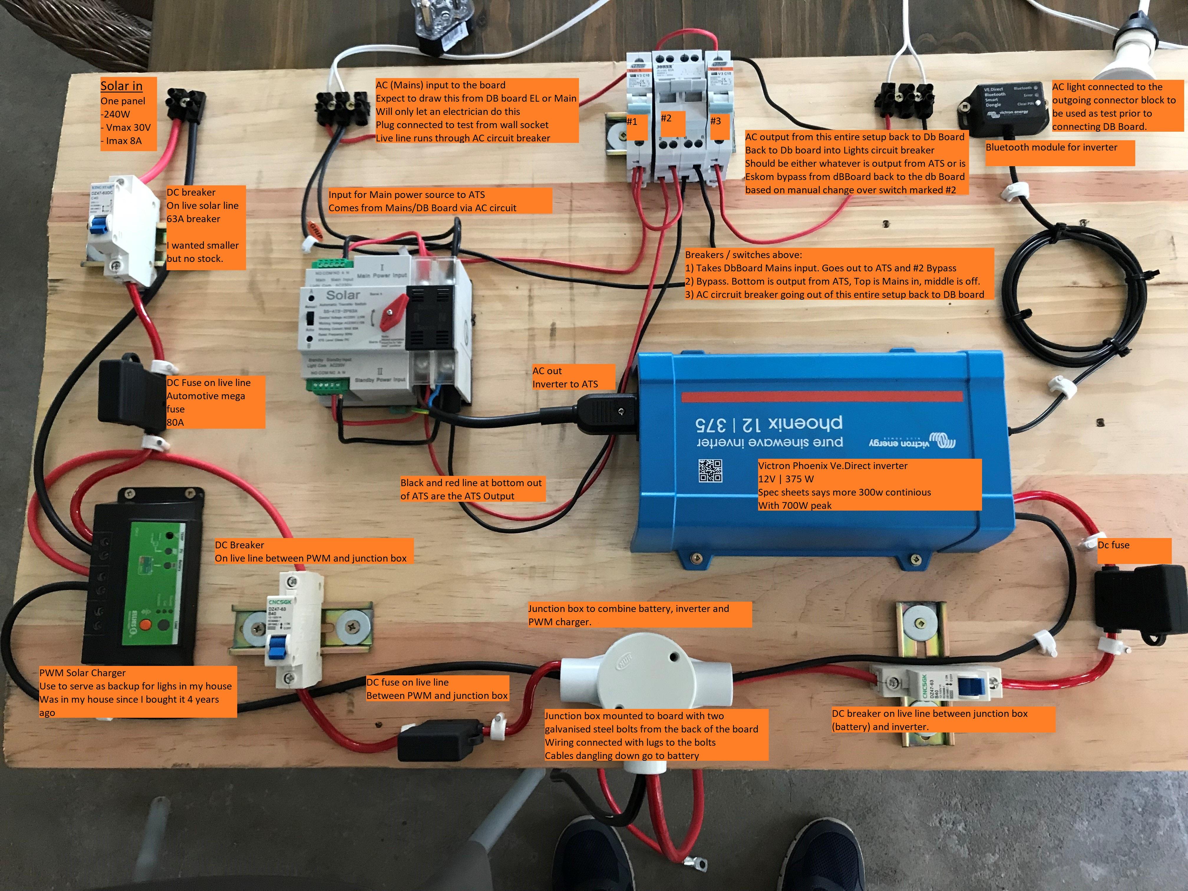
OK, so here's the labelled version with description of what I'm trying to do .... This wooden board setup below has one solar input, one mains AC input and one AC output. On the board itself is obviously a small inverter, ATS, solar charger and various breakers and fuses.

-
This is unlabelled version of the backup setup I'm trying to build. It's a wooden board meant to be mounted against the wall in the garage close by the DB Board. This wooden board setup below has one solar input, one mains AC input and one AC output. On the board itself is obviously a small inverter, ATS, solar charger and various breakers and fuses. The labelled version of this picture I'll post shortly tries to explain what I'm trying to do here....

-
OK... Let me try some uploads:
-
Will do... Little bit scared to have that open for scrutiny.. but fair enough I guess.
-
One other test I want to do sometime this week is: might be that my inverter is actually powerful enough to activate the switch with peak power but I might be losing some power with my cabling / connections. I'm not knowledgeable on electricity so "to be safe and proper" I put DC breakers and fuses all over the place; specifically one DC breaker (63A) on the live line between the battery and inverter and also a DC fuse (80A) on the same line. The cable is thick. But maybe I screwed something up there.
-
Hi No generator to test. I guess I could quickly wire up the mains and backup to two separate wall sockets and switch one off to see... But with my inverter reporting an "overload alarm" I was assuming it is safe to assume that, that is the problem. I'll do a wire up of two plugs and connect to the ATS to make 100% sure the ATS works well. One thing I can tell you, based on switching back from backup to mains, is that it switches helluva quick. The spec sheet for ATS claims <50ms. Not sure if that response time requires a bit more power. I'm trying to figure out whether to replace the inverter with a bigger one or find another ATS. Another ATS will surely be cheaper but, then I still don't know if my 375 (700w peak) inverter will switch a slower ATS. Or maybe just buy a bigger inverter at higher cost, but then I'm still guessing what size to get.
-
I thought an ATS would be the correct, safe and easy answer. I'm not very knowledgeable on electricity and wouldn't want to DIY too much when connecting with mains power, especially in someone else's house.
-
Morning, Charging happens with an old 240W solar panel and PWM charge controller I had lying around. Well, not lying around, the panel and PWM use to serve a similar purpose in my own house until I installed full solar a few weeks ago so I'm trying to put together a lights backup for someone else. Seems to work well except for the ATS not switching in all directions. Thanks
-
Good day all, Hope you all are well. I'm setting up a small load shedding solution for a low power use-case (around 250w at max, lower most of the time). The setup in general, is a 375w Victron Phoenix inverter, coupled to a 12v 100ah battery and an Automatic Transfer Switch. Load is carried by mains power but should switch automatically to inverter when mains drops. The ATS I bought is this one: (2 pole, 63A ) SOLAR Automatic Transfer Switch (ATS) 2P 63A (sircony.co.za) I'm having some trouble and thought I could perhaps get some useful info or pointers here. The problem is that the switch does not automatically switch from mains power to standby power; however it can automatically switch back from standby to mains. I suspect that the problem is that the inverter I'm using is too small to activate the switch. In my setup, I'm using a 375W Victron Phoenix to power a few lights. When switching from mains to backup, the ATS just buzzes but doesn't switch. It appears to me as if the inverter also records an "overload alarm". There is no load connected, it's just testing the switch for now. I peformed a few varying tests with a small load also and another (stronger / newer) battery - sall the same results. My question is: for this ATS, how much surge power is needed to activate the switch? I will probably end up having to buy a larger inverter and don't want to guess. Alternatively, could I have perhaps connected the ATS wrong or is there another type/range of ATS more suited to low power use cases (that is also in stock somewhere in country)? The Victron inverter I'm currently using is rated for 700W peak, so I guess the ATS' surge is more than that when switching. Thanks Christoff
-
Thanks.... I saw that the other day while in an ACDC express - like a little orange screw. I wanted to buy a 12v one specifically for this purpose but the sales guy on the floor told me that according to him, all those adjustments have been disabled before the devices are put on the shelves. I was really confused by that statement but he assured me he had a conversation with their technical crew at ACDC about this very topic only a few days before. Maybe I'll just go get a 12V version and test it out. Thanks a mil