


Christoff83
Members
-
Joined
-
Last visited
Everything posted by Christoff83
-
Hi all, As with many previous threads around this topic on this forum, and other forums, I’m wondering whether to install 5kw or 8kw inverter. Having read quite a few threads and articles, I want to try summarize my view on it. For me, the top key takeaways from these discussions are: Understanding the difference between inverting capacity and passthrough capacity. When an inverter is advertised as 5kw, typically that refers to its continuous “inverting capability” meaning – to me – that while eskom power is off, you cannot carry more than 5kw load; or even while power (eskom) is on, you cannot contribute more than 5kw from your solar array or battery. BUT, a 5kw inverter does not mean that you are overall limited to run your house at a maximum of 5 kw all the time. I see many manufacturers refer to a continuous AC pass-through power or current. Today I’ve seen a few as 50A which – again, to me – means 230v AC @ 50A means around 11.5kw load you can carry in your house WHERE a theoretical maximum of 5kw could come from your solar array or battery. Most high-quality inverters are informally known as “true hybrid inverters” which means in the above scenario, your house can run up to a total of 11.5 kw where the first 5kw will come from your inverting capacity (solar or battery) and the shortfall from 5 to 11.5 will be “blended” from eskom. This of course assumes eskom is on and that you also have 5kw available from your solar array or battery. While living with higher self-consumption, some people prefer to parallel two 5kw’s instead of going for a single 8kw because: Lower entry cost (you can start with one 5kw and add another later) Redundancy. If an inverter fails, chances are you’ll have another while repairing… More MPPT’s with added capacity and flexibility (depending on the brand). Lower noise levels on the 5kw potentially. Have wheels, will travel. When estimating usage, one can probably add 20-30% on your current usage as one would be inclined to use electricity more freely when it becomes free off sun power. So two questions for the audience: Would you agree / disagree with my key takeaways above? In light of the above, assuming it’s more or less correct, is there anyone who implemented a 5kw inverter who wished they had gone for 8 kw or anyone who had gone for a 8kw and realized that a 5kw would have been sufficient? Any other comments welcome. Cheers
-
Hi all, Remember those first NL power packs? At least 10 years old now. With current bouts of loadshedding and me still working on a home solar solution, I need to power the living room “UPS”. My UPS these days is a standalone inverter (375w) and standalone charger both connected to the battery. I was thinking that since my old NL power pack has an old battery I could probably have it do service in the living room as well working with my standalone inverter and charger. Regarding the two Anderson plugs on that NL box, my understanding / recollection and recent research about these ports is as follows: The red Anderson plug: · While camping and overlanding, this use to be connected to the vehicle alternator while driving. · This is an input only i.e. input to the battery inside the NL box. · This plug has some electronics / regulator between it and the battery used for charging. They grey Anderson plug: · Meant for higher outputs while camping which never/rarely used. · This is an input or an output. · Connected directly to the battery i.e. no regulator, charger or other circuit involved. Now if you wish to charge the battery inside the NL box without sliding open the box you have the following two options in my mind: · Intelligent charger plugged into a wall socket and going into the grey Anderson plug – this will allow the charger to talk directly to the battery as if it was clamped on. · Or, if you want to use the red plug instead (which opens the grey Anderson for an output), you cannot use the wall charger as this will confuse or interfere with the circuits behind the red Anderson plug. What might work is one of those AC>DC power supplies people use with CCTV systems etc. so that the electronic circuits inside the NL basically see it as an incoming voltage from an alternator. Most of those power supplies are 12v or 24v which I guess will be too low and too high. ACDC Express does have a 15V 10A one. That’s close to a car alternator right? And this would allow the NL to charge the battery as if driving. Anyone else done something similar?
-
So far working OK... The absorption charge seems to get stuck close to 3A though while a load is on. I charged it full to "storage" stage once while I left the inverter off. Maybe the time windows between loadshedding are not long enough to allow a proper full charge while under load. Cheers
-
Thank you for this. For now, I'll leave it as is and monitor the heat levels and battery state of charge. I feel this system, even though small, is oversized for the use case - the load is really small. It still is an interesting topic to me though; and it still confuses me quite a bit. To my knowledge, from reading similar articles to the one provided, a battery CANNOT be charged and discharged at the same time. That makes sense, because DC current can only flow one way, right? So, that means the load AND the battery will both draw power from the charger at the same time. If the charger is strong enough, it will power the load and charge the battery. If the battery is full, the charger will power the load. If the charger is switched off; or eskom drops, then the load immediately draws power from the battery via the inverter. Now that's all good and I'm happy with that. Here's my problem (or rather point of confusion): most modern chargers are "smart chargers" right? They have these special algorhythms with special charging stages, each stage with a very specific voltage and current - all designed to best manage the battery. Now, how does the smart charger get these special charge parameters to the battery with an active load? Does the load not interfere and basically void all these smart charge stages? Anyway, thanks for the response. For now I'll leave the setup as is and keep an eye out for a good standalone ATS. The ones with a quick enough transfer time (to keep my network gear on during transfer), seem to go for about R1.5k to R2k. I am also looking into a complete solar setup for the house which will render this little backup solution redundant. Cheers
-
Hi all, In my livingroom at home, I’m running a small battery backup for the TV, wifi and occasional laptop or other small device. The setup is: Victron 375va standalone inverter, Victron 15A AC charger and a 105 ah, semi-deep cycle battery. Does this setup need an ATS (Automatic Transfer Switch) or can I permanently leave the charger in the wall socket connected to the battery, the inverter connected to the battery and the wifi + TV connected to the inverter? My reason for running this backup as “separates” instead of a convenient all-in-one UPS like a Mecer or something is that I believe those UPS devices use cheap/bad quality inverters and especially chargers inside which are real bad for battery longevity. Will probably start a thread on that soon but for now, I need to know comments/opinions on the ATS requirement please. Thanks
-
Thanks for confirmation. That means to me that this setup is connected wrong or I followed the pipes wrong. Really hoping someone here can recommend a proper specialist or plumber who can help me physically inspect the setup properly (at a standard callout fee ofcourse). thanks again
-
Hi all I have a Stuhmr 5kw heatpump connected to my home geyser. Bought the house with this setup 4 years ago. I do still use the geyser element for heating while the heatpump remains off. There’s something wrong with this heatpump setup - everything seemingly runs fine but to me, the pump seems confused about water temperatures and runs itself itself flatout into exhaustion and a protection error code. I had various electricians, plumbers and “heatpump” specialists out but no one can fix it. Here’s my take on it: - Following all the pipes around the geyser and pump, municipal supply and feed pipes to the bathrooms, it looks to me as if the heatpump inlet is a shared pipe from the municipal supply. - Reading the heatpump manual and diagrams, the water temperature sensor sits on this inlet. - That’s why I believe the setup is wrong. The temp sensor would always pick up cold water from fresh municipal supply. - In my mind, the heatpump’s water temp sensor should detect how hot/cold is the water coming out of the geyser - not so? - This I believe is why the heatpump runs and runs and runs itself into exhaustion and an error code - it doesn’t know that the water in the geyser is actually hot. Now, it might be that I misunderstand the concept of heatpumps, or made a mistake in following the water pipes or made a mistake in reading the heatpump diagrams. Can anyone recommend a heatpump specialist who can do a callout and come physically inspect my setup to confirm if this is actually the problem? Pretoria-east Thanks! Christoff
-
That’s probably it then …

-
Hi all, hope everyone is well. My solar journey starts here… potentially converting my existing geyser to a standalone solar setup. I’m currently looking at the Geyserwise solar conversion kits (where solar is converted to electricity and heats the specialised element). First trick: how do I know what size geyser I have? Most probably 200L or maybe 150L. I’m failing to google this and the kits are apparently VERY specific to your size geyser. Thanks! Christoff
-
Hi I dont know about that product specifically, but just a sanity check to begin with: to power a fridge you'll need pure sine wave, right?
-
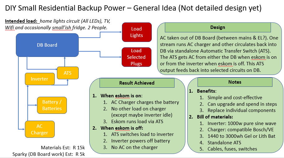
Hi all, Hope everyone is doing well. I would like to propose a small backup power system and see what you think. It's not a design yet, just a rough idea for now. If you don't tell me here that it's a terrible idea, I'll probably continue to refine it into a more detailed design and post again. Here's the use case: Backup power for small residential use. Two retired people at home. Mostly loadshedding and some extended outages. There's an exercise ongoing at the moment using a kill-a-watt meter to measure expected load. I expect it to be small though. 300-500W. We need backup power for Home interior lights (standard LED bulbs). Not many lights are on at a time (only 2 people). TV station: it's one 42" TV, dstv, wifi. Selectively, one fridge. Fairly small fridge, no freezer. Probably not used during loadshedding but when there's an extended outage we want the option to cool down the fridge again once or twice. Requirement is to get something up and running as cost-effective as possible. We could always improve, extend and expand later on. That means though the system must be designed now to cater for that. Typical Hybrid solar solutions (Sunsynk / Deye etc) are off the table for now due to cost. Even the most cost effective solutions 3KW/4kw with Growatt and a few panels are too expensive for now. FiveStar has some hybrid inverter solar solutions that are more cost effective BUT, still too costly and ... anyone trust FiveStart? You do get these mobile inverter solutions on a trolley. Might be an option but those are already 50-60% of the maximum I can spend now and they typically only come with one 12v 100ah cheap battery, weak chargers etc. So here's the plan: Disclaimer: - I'm a complete electricity NOOB. Hardly know my amps from my volts. - I won't personally fiddle in the DB Board. Will get a sparky for that. Any thoughts? Thanks Christoff
-
Thanks for all the info. Lately I think these vehicles make more and more sense for my household... or households such as mine. Consider this: We have two vehicles. Both ice. Thanks to covid changing the world, both the wife and I work from home now. Zero daily commute to work. We are lucky enough to have the school in our neighborhood, literally 300m from our house. The SPAR is 500m. A good estimate would be that 90% of our driving is school run and shops - everything so close. I don't think - for daily commute type stuff - we do more than one or two short trips per day. Unless I'm missing some critical detail, it would make sense for us to change one of two vehicles for full electric (not hybrid). For holidays, weekend trips or any other occasional longer driving, there is still one proper diesel powered SUV. What I don't know is life expectancy of batteries and costs related to that. This could become a deep rabbit hole. Thanks again for the info!
-
Hi all, Hope everyone is well. I have a strange request for you today. I need you to help me understand the lighting system in my house. So, it’s a normal downlight system with one exception – and this is the part that causes confusion – the downlights have a solar & battery backup for loadshedding that works well but it raises questions in my mind. Let me share what I DO know: · Downlights are MR16 GU5 (12V AC DC) and all work off the normal light switches. · Solar panel on roof, connected to charge controller in roof connected to 100ah in roof. · Also in the roof is a 12V Power Supply (Xytron GK-250-12). Ouput 12VDC, 21A. · From the main DB board, 230V is connected to this power supply. · The power supply also has 3 pairs of V+ and G which I assume is DC out channels with a mess of wires connected. Here’s what I’m trying to figure out: · How is the battery connected into this system? When AC goes off there’s a seamless transition – lights stay on and still work off the normal light switches. From the charge controller, a set of wires come off the “Load” terminal into the mess of wires around the 12V power supply but I can’t tell where they end up or what they’re connected to. Surely they can’t just be spliced onto the Power Supply’s output? The battery will also draw too much on the supply if not fully charged. · How the fuuuudge are the normal light switches integrated into this system? Normally, DB board output goes to the lightswitch panel for a certain room and then out to the light itself. In my case, I assume, there is only one output from the DB board to the central 12V power supply and from there, there is an ouput to each light switch for each room and then from there a line out to each group of downlights for that light switch. That makes sense, BUT, does that mean I have 12V lines connected into the house’s light switch conduits and switches? Not CoC? There is no transformer at the downlight unit itself. Not sure if there’s anyone around here who may have a similar setup or perhaps just know what conventions are with such a setup. I can’t figure it out. Reasons for me asking is this: I’m curious and always want to understand everything (especially my own house), if my house has compliance issues I’ll need to fix it, I want to expand the system to one or two rooms that don’t have the downlights, I’m considering conversion to GU10 and I’m considering a full-house solar system and don’t know how that will impact the current lights. Any thoughts? Much appreciated
-
Hi all, My first post. Hoping to tackle a few small projects at home + at parents’ home and I will definitely need some advice. These projects are mostly focused on backup power for essential items, led lighting and CCTV. My knowledge on these subjects is minimal. Motivation behind planning the projects is primarily security based but also I’m considering a few strange twists which come from curiosity. So, the project I’m considering at the parent’s house involves 4 things: 1. Network backup power > Basically keep the fibre and wifi running at least during load shedding and potentially for longer outages. Probably some off-the-shelf UPS involved here. 2. LED Lights outside > Basic LED lighting outside the house for security purposes, especially during load shedding and other outages. No need to be able to play cricket under these lights – just need to see what’s going on around the house from the inside. Need some good coverage all around the house without adding too much (or any) electricity costs and potentially even add some smart controls to it (at least an easy remote switch). 3. Secondary indoor lighting system > This is where I get a bit crazy. I want to enable a secondary lighting system inside the house mostly as backup for load shedding. I’m saying “secondary” because I have no desire to tamper with the house’s wiring system (i.e. the primary lights system). 4. CCTV > This becomes straight forward again. A few CCTV cameras around the outside of the house. Requirements are they work during load shedding and don’t use wifi for video transmission. There are a few basic design principles to consider. These are: · Implement solutions for all 4 problem statements above separately, i.e. independent from each other or combined in groups for example power network backup and CCTV together while running the indoor and outdoor lights on a separate system. · Make use of 22V devices (LEDs, indoor lights etc) and run them all off a big UPS/inverter i.e. a centrally powered solution running everything off mains power and cutting over to UPS battery + inverter when mains fails. · Power everything centrally still but keep it all off grid with 12V LEDs and devices, a big battery and solar panels. No need for an inverter and save on mains power costs. I’m leaning towards: · Doing the network backup and CCTV system together on mains and one UPS. · Running the lights indoor secondary system + ourdoor off large battery & solar only. I already have considered quite a few lower level solution details but this post got really long so I cut those out for now. So then that's my very long introduction story. Probably not ideal to discuss the whole project here in the intro thread. I will probably repost most of this and my additional solution details in a more suitable forum area OR, break it up into smaller sub projects and ask more specific advice in those relevant sections on the forum. Thanks Christoff

