Chris M
Members
-
Joined
-
Last visited
-
Hi, thanks for your suggestions. My PC is connected via RS232, so a write should work - but I'll test with the SOH first. As for a firmware update: the warranty has expired anyhow. About the version you can share with me - are you refering to the PBMS tool or to the firmware?
-
Thank you I84ris for clarifying the protection vs fault trigger. Got it! And TaliaB is right: the values in the "Pack Current" column are all in milli amps - meaning that the load registered in the second line was indeed 13.57 Amps. Which is well below the 110 Amp limit for triggering an OC protect... In fact, due to the small size of the inverter connected to the battery it would be pretty much impossible for me to even reach the 110 Amp: I am using a 2 kw RCT inverter which under normal conditions would draw a max of 2000 Watts / 24 Volt = 83 Amp. Anyhow: the BMS does register an OCP. There's three possible explanations for this to happen that I can think of. 1) The BMS is simply faulty or set incorrectly. 2) Something between the battery and the inverter triggers the OCP. I do have a Victron solar charger for my second panel array which independently can feed a max of 24 Volt / 20 Amps into the battery - but it will of course only do so during daytime. The OCPs registered in lines 1-11 have all occurred at night though, so I decided to rule out the Victron as a potential cause for the OCPs which in any event would have to be an over charging event, not an over load event. But all the OCPs registered in the log have occurred under load condition, not under charge condition. 3) In theory this inverter model will tolerate a surge of up to 4000 Watt for a maximum of 5 seconds in its default setting. However, I set the relevant parameter (= overload bypass) so that the RCT will automatically switch over to utility the moment 2 kw load are exceeded (a scenario which I then tested: it works faultlessly). The transfer time of the RCT for such a switch over is given as 10-20 milliseconds - which again is well below the delay times of the battery BMS: With options 2 and 3 being ruled out my conclusion is that in all likelihood the BMS is the culprit. But then maybe there's something wrong in my logic...

-
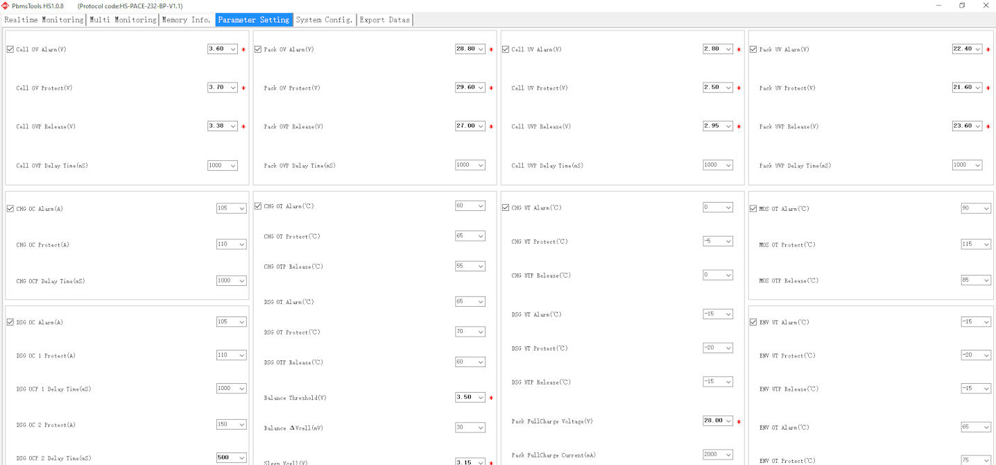
I'm experiencing a similar problem with a SVolt LiFePO4 battery (25.6 Volt / 2.71 kwh): the battery keeps on shutting down at random regardless of actual load or SOC. I accessed the BMS memory via the PBMS software and got a reading that's puzzling to me in that it shows instances of a "protect", but never an actual "fault": I then checked the settings and found that the PBMS indicates a number of parameters as being "out of range" (marked by an asterix) - but when I then do a reset I get the exact same settings: Be this as it may: from the first table I can see that the battery cells were always within the set OV/UV threshholds. Does anyone have an idea how one can solve this puzzle? Chris


-
Ah, here we go again... No more OVPs, but another OCP when there was minimal load. What's even more perplexing is that the OCP occured immediately AFTER an appliance responsible for a load of some 700 Watts switched off, thus REDUCING the current drawn by the inverter from the battery by some 30 Amps. What also doesn't make sense is that in order for the BMS to trigger an OCP I would need to put a massive overload onto the inverter: The SVolt is supposed to be able to deliver a current of up to 100 Amps, so I suppose its OCP If maxed out my small RCT 2 KW / 24 Volt inverter will draw 83 Amps The RCT can handle a power surge of 150% for 5 seconds - so under extreme conditions a load of 3 KW which would then result in a current of 125 Amps to be drawn from the battery for a max of 5 seconds before the inverter's overload protection kicks in I simulated the above scenario by putting a 2500 Watt load onto the inverter - it behaved exactly as it should and cut out after 5 seconds while the BMS did not trigger an OCP. A couple of questions then: I tried to find out from the SVolt manual at which threshhold an OCP will be triggered and what the latency of the BMS might be, but there's no information on this. Does anybody have an idea? Is there perhaps a way to reset / recalibrate the battery's BMS? I tried its reset button but that doesn't do anything As there is no way to access the BMS settings via the battery display I thought it might be possible to get into it via a USB to RS232 cable. Any advice on this? I was not supplied with such a cable and would need to get the correct one first. The supplier says that they don't provide it on purpose as the manufacturer doesn't want users to tamper with the BMS, which is at odds with the manual which tells you to install PMS Tools on your computer. Any hints would be greatly appreciated!
-
Dear All, I'm happy to report that thanks to Talia's information about the Voltronics common over-shooting of the set max voltage and Mr.Beauvedere's input it seems I have eventually resolved the issue. I set the values on both chargers significantly lower than suggested by the SVolt manual: on the RCT: Bulk = 27.5 V, Float= 27.2 V, 'Back to utility'=25.5 V, 'Back to battery'=27 V on the Victron: Absorption = 27.39V, Float = 27.2 V. (There's no option to set Bulk voltage here) This has now worked faultlessly for 3 days and the battery is being discharged down to 28% SOC and then charged to a max of 93 % - no more OVPs since. In the final analysis I guess it was in fact the much higher bulk settings on both the MUST and the Victron where I originally had programmed Float = 28 V as per the SVolt manual. OK, it's still early days, but I'm cautiously optimistic for once 😉 In the next step I will now exchange the RCT again for the MUST and test that with the same settings. The supplier has tested the MUST and claims it is absolutely faultless, plus they set what they claim to be the correct values. In previous communication with their texchnical expert they had suggested that I use Bulk charging = 28v , float charging = 27.2v and battery cutoff volts = 23.2v. However, in my installation these settings did not work with the MUST, and I guess that Bulk= 28 V is pushing it - hence the OVPs. Anyway, many thanks for everyone's input! I exchanged countless eMails with the supplier, the SVolt and the MUST manufacturers, and none of them were able to help. But you guys were great!
-
Yes, but we're well below that as the system only provides power to lights and essentials, plus the pool pump. Even if everything is on we will only reach a max of 1.5 kw = 63 Amps, plus the RCT inverter shuts down when you exceed 2kw load anyway (I tested that). But initially I thought along the same line as the faults seem to coincide with the start of the late afternoon run cycle of the pump: so I replaced the capacitor on the 650 Watt motor thinking that it might create extremely short power surges on start up which theoretically could reach up to way above 2kw, but wouldn't trigger the respective circuit breaker due to latency. Nice theory, but the problem persisted. I'll nevertheless give the theory another go and now just switch the pump over to utility for a day or two and see what happens then.
-
Thank you both, Beauvedere and Talia - wow, 111 OCs is indeed a lot! I have temporarily replaced the MUST with my old RCT to rule out any inverter fault; the problem occurs less frequently, but remains popping up. As for the inverter charger settings: at current it is set to bulk = 27.5 Volt, float = 27.2 Volt. I also disenabled both PC arrays as well as cut the link between the secondary Victron SC and the battery, so the only charge current comes from the inverter - that worked ok for 2 hs, then another shut down. OVP count remained at 111 but OCP went up from 37 to 38. As for charger voltage: the battery display shows 26.95 V at 82.71 SOC while the inverter measures the battery as having/being charged at between 27 and 27.2 Volts. However, a control measurement with my multimeter only gives me 26.0 at the inverter's battery cable terminals, yet 27.4 at the battery's end (I'm running 25 mm cables, 1.8m long and the max combined charging amps of the small RCT is set to 50 Amps, the utility charger to 20 Amps). Finally , battery cell voltages 1 to 8 are all between 3367 and 3370 mV. What a conundrum...🤔🤔🤔
-
Thanks, got it.
-
Thank you! The readings I get at current are OVP: 111 SCP: 4 OCP: 37 UVP: 2 But unfortunately there is no documentation as to what the numbers mean - are these codes, incident counts, values? Would you have any idea?
-
Dear Talia, many thanks, that (= "Voltronic inverters are famous to overshoot the voltage setting when battery is close to 100%soc with intermittent cloud and sun") makes a lot of sense. Unfortunately my SVolt Manual gives no explanation on what the various abbreviations (like: OVP, SCP, UVP etc.) mean and how to interpret the values - for example, what does "OVP: 8" exactly stand for? Do you perhaps know where I can find more detailed information on this? Sorry for the trivial question...
-
I am experiencing erratic behavior (in particular, sudden battery shut-down) in an SVolt 2.71 kwH LiIon battery which is connected in parallel to a MUST 3.6 kw hybrid inverter with a mains feed and a PV feed from Solar Array 1, and a Victron 30/100 solar charger with a PV feed from Solar Array 2 The conditions under which the battery pack suddenly shuts down are as follows: the battery pack has an SOC of well above 50% right up to 100% the PV voltage on Solar Array 2 drops from one moment to the next, typically in the late afternoon when it is cloudy and this array suddenly gets no more sun at all. On a cloudless day, i.e. when the transition from sun to no sun is gradual, nothing will happen. The battery shuts down without any warning and its red light for "fault" flashes. The entire system then shuts down. The log on the Victron charger shows that a significant voltage drop down to less than 24 Volt has occured - but it is impossible to tell whether that drop occurred before the shut-down (and thus due to the sudden drop in PV input) or after the system shut-down (i.e., due to the battery having been disconnected by its BMS) After a moment the battery pack will then automatically restart, and on second or third attempt so will the inverter. All readings will now go back to normal. My first try was to replace the inverter with a smaller RCT 2kw which I had run for 4 years using the same configuration, but originally with an AGM 24 Volt battery pack. That configuration worked perfectly, but then also started giving me trouble once I switched from the simple and robust AGM setup to the SVolt lithium pack. I thought that the RCT had reached the end of its life and therefore replaced it with the MUST - but actually matters got much worse. I must confess that I then blamed the MUST inverter for it - but it has been tested by the supplier and was found to be faultless. Moreover, when I reverted to the old RCT inverter for comparison the same problem eventually occurred - though not as often (maybe the simpler and smaller inverter is just not as sensitive and does not interfer with the battery pack as easily). My last attempts at problem finding have now been the following: (1) I isolated the Victron's second solar array at the combiner box, but left the Victron solar charger as such connected to the battery. Again, I experienced a shut down. (2) Finally I then also completely isolated the Victron from the battery. So far, so good ... Two questions: One, does anyone have a clue what might be going on here? I read up on this type of configuration and it is apparently not unusual to run a system in this way - but maybe the SVolt's BMS is just so sensitive that it responds to some 'conflicting messages' being sent by the two independent MPPTs. Two, would it probably help if I were able to establish a BMS cable link between the inverter and the battery pack? It would enable the inverter to operate based on accurate readings from the battery; however, the second MPPT in the Victron - which seems to play a major role in the problem scenario - would of course still run independently. All I could do on that side is to experiment with the Victron's charger settings (which are currently on LiIon, but could be set more conservatively, e.g. to lower values). I'd appreciate some help with this mystery!
-
Am I correct: the RJ11 to RS232 is for the connection between the SVolt battery and your PC which you need to configure the PBMS on the battery to get it to talk to the Must Inverter. - If so: how can I then get from RS232 out to USB in on my PC? In
-
Hi, I'd very much appreciate some expert advice on the correct panel configuration for my rather lean 2 KVA system with inbuilt MPPT. Context: My system is small and low budget compared to the very, very impressive stuff I've seen here (e.g., I'm using 4x 100Ah AGM batteries, no fancy Lithium Ion, and a small 2KVA RCT inverter). And I also have no plan to go off-grid: I merely installed this little setup 6 months ago to prepare our 2-person private household for load shedding, and to date it has been working like a charm. We practically don't feel load shedding other than having to check when we can run certain appliances. All the essential low consumption items such as lights, fridge etc. are on a dedicated DB circuit that can be separated from the mains supply via a changeover switch. The batteries are configured to output 24 Volt, so their total capacity is 24 V x 200 A = 4.8 Kw, and I set the inverter to cut out automatically at a max of 50% capacity usage. We never got anywhere near that: out of curiosity I isolated the inverter from the AC supply and let the system run for 12 h hours using whatever I wanted to use (lights, TV, PC etc. to which my wife then accidentally added a 1.8 kw hair dryer for 10 minutes...) After that I could only measure a 20% capacity loss = so over 12 hs just 0.96 kw used or 80W / h. Makes sense when I calculate back from our metered electricity consumption: we normally use about 20 kwh/d = 833 w/h INCLUDING all the bigger appliances, geyser top-up heating, pool pump etc. - So it seems to me that all in all my little system is right sized to begin with. Requirements: OK, so I now want to add some solar panels, and I also want to stick to my 'lean engineering' approach. These are my requirements: a) Be able to charge the batteries from solar via the inverter during the day if needs be. Let's assume continuous stage 6 load shedding as worst case: if we draw 80W / h over 6 hs from the batteries we'll use 480W per day. So if I can install 1000 W panel capacity and conditions are ideal I should be able to make it and recharge my battery bank to 90% plus. (Of course realistically I should be preparing for stage 16 🤓 .) - But more than that I want to be able to... b) ... add our 550 w pool pump to the dedicated circuit and power it from solar when there isn't load shedding - because in our household the pool pump has turned out to be the single biggest consumer of electricity. And this while it is practically the only machine that is absolutely guaranteed to run only during the day.... The pump is set to run for 4 h/d, so that means 2.2 kwh consumption per day. Seems realistic to cover that need from a 1kw panel array too, yes? So my overall requirements are really quite limited - namely to be able to cover the energy requirements of either a) or b). Configuration options Here are the inverter parameters: Inverter: RCT-AXVM2K, 24 Volt Max PV Array OC Voltage = 102Vdc PV Array MPPT Range = 30-80Vdc Rated Power Solar Charger = 1000 W Option a) My initial idea was to use 2x JA Solar 540W in series to obtain 1 KW under ideal conditions, with high voltage and amps as low as possible. But I now realise that the combined max Vmp could then reach 2 x 41.64 = 83.28 Volt, which exceeds the 30-80 Volt range specified for the MPPT. Of course only theoretically and on a very cold day, but still... Question 1: Are the theoretical 3.28 Volts something to worry about? Option b) Use 3 x JA Solar 365W in parallel . This configuration would then give me the 1 KW output at a comfortable, if not even rather low Vmp = 33.96V which is at the bottom end of the MPPT range. But more problematic perhaps is that it would require me to also run cables to my inverter that can handle a whopping 3 x 10.75 = 32.25 Amp current if need be, if my maths is correct. Question 2: Is this a (more) advisable approach? Option c) Downscale to a 2 x 2 series¶llel configuration that uses 250 - 300 W panels. Drawback seems to be a rather low efficiency in the 18% region, plus I didn't find any 250 W panels here at the power-forum store... Many thanks for your patience in reading through all of this! Chris