Georg594
Members
-
Joined
-
Last visited
Everything posted by Georg594
-
My House is also not ideal oriented.... This is my solution: 6x trina 400w

-
Is there any interest to get a alternatively calculation of battery level ? On my system lead acid ( 775 Ah pzs ) it is only voltage from where its calculated, this is shit . If there is a high load on batteries soc goes down to 60% in seconds. Actually i am working on victron bmv 712 data integration in the Axpert firmware to get it accurate & no more trouble with float / bulk switch Is someone here who could need this software?
-
The installation of a 30mA RCD before any inverter is not recommend,since nearly every On or Off grid is not isolated. (This cause continues small currents to earth ) Anything before the Inverter it just makes no sense for user protection, its just to prevent fire if any isolation fails. The normal way to install hybrid inverter is: This is for the input of the Inverter: 300mA( 100mA is also ok on small ones) RCD before the Inverter . At the output there you can use the 30mA RCD for user protection. If you got a standard On grid : Take a separate cable to the Inverter with overcurrent protection and RCD with 100mA or 300mA .( At this wire no plug or connection to any other thing ) By the way: RCD typ AC is not recommend for Hightech inverter since there is a chance of pulsed and dc current to earth.
-
With help supply connected it seems to be the better the higher ....175V was the best compromise for me when help supply was connected . In normal operating you Gain nothing with a higher mppt min voltage, this is just a easier step for the help supply to Start. Without help supply we could go below the original 90v without any power loss.
-
The description seems to be wrong, i bought an Easun and in the ebay description was like your screenshot, but in the pictures there it was explained that the 120A are combined. Or maybe did you really have better hardware in your inverter? Did you get 120A solar charge with original firmware?

-
In the datasheet of the axpert 8kw there is explained that grid to battery charge is up to 120A and solar to battery up to 80A And there is a limit for each mppt of 4000w .
-
Hi, At least 120V seems to work best with no hardware modification. the value of 120V is taken for maximum compatibility. (In the 8kw thread, a 100V firmware does not bring the greatest improvement, it works best from around 115V)
-
First Release for 7.2KW Axpert Firmware still based on 90.19 It got the same improvements like my 8KW version except the Shade Management. Mppt minimum voltage is set to 120V (the new range is 120V to 450V) Firmware shows up as 90.20 7.2KW.zip
-
46.08 is compatible with 90.06 ... Did you have first or second generation?( Removable display = first , round integrated= second) 90.06 is only for first generation. On my second inverter from Easun i did the same thing, flashed up to 90.06 without any problems. If you could test to flash a 90.06 and when it runs I will make you a firmware with mppt fix and F90 deactivated.
-
Did you check internal Fuse ? Direct behind the ac input there is one .(need to open the big cover) Axpert has simple fuse, if blown needs to be replaced. The clones have a resettable one.
-
I cut off the two small wire from mppt board and adapt them to the two big outputs from the mppt pcb . But this let the inverter run constantly and like coulomb said triple energy conversion losses .
-
Forgot to say the test was to supply the help pcb from dc bus directly
-
The reason for disconnect the AC plug is when you disconnect Solar it pulls constantly around 60 watts from grid , in every situation and every mode (usb,sub,sbu) . To originally avoid this there is a priority logic (in hardware)on the help supply so solar prio1 , ac prio2. So if you don't disconnect both the grid meter shows around 1.5kwh per day. Are you shure with bus - and bus + ? Mine has 2 diodes ( pv1+ diode + pv2+ diode , the other wire is pv -. I testet it on mine and then the inverter was not able to switch of because of the information from the 4 pin plug on the help pcb is : stay on .
-
The " help" supply is using around 40 watts from solar when connected and pulls down the voltage so that mppt point cannot be used . (that does not mean that the 40 watts are not consumed) If you calculate the 40 watts in general and the higher voltage because of mppt point is now always found by firmware the diagram makes also sence to me. @ Coulomb Where do you see dramatic increase in power ? Did i miss something? Biggest incress in watt is from 38watt to 137watt
-
On my axpert 8kw all modes work normal, ( solar & AC pulled off). But what i note was a charging from grid to battery when solar power is low , the measurements are so wrong of my axpert that it thought there is 100 or 200 w solar power available and because the dc bus is shared for mppt & charger the power comes from grid to the battery. The power moving in the dc bus is just a firmware calculation & there is no measurement of current flow, just a logical firmware decision.... ....if it measures 200w solar power input it will take this power out with the charger from the dc bus but the power in real comes from grid . The measurements are sometimes way off reality.....real was 9 watt but axpert shows 71w
-
I got mine completely disabled and pulled of both plugs ( ac and solar) Works best , minimized consumption from ac and nice mppt regulation, but beware if you got a small battery , in mode SUB mine isnt charging the battery when load is greater than pv input power.....in this state it draws around 1.5A from the battery.
-
F90 is a " clone " detection but sometimes just a corrupt eeprom. The firmware is based on 90.19 and shows this too. It has F90 patch applied and mppt optimized like in my 8kw firmware ( these versions are nearly the same)
-
Try this: 7.2KW.zip
-
This is how the regulation looks on the axpert max display when no better mppt point could be found VID_20221219_135909_1~3_1.mp4
-
Edit: The video is made with solar plug pulled off from the help supply
-
Made a video to show how it works. The multimeter shows pv input Voltage which comes from a 350v supply but i connect a 40w 230v halogen lamp in series to it. (This is nearly the same situation if there is a shadow on the pv moduls from the electric view) Display on axpert shows input Watt. The video shows the sequence of regulation. VID_20221215_192321_1_1.mp4
-
Development is still going on and this is my next evolution step. SHADOW MANAGEMENT INTRO : Why do we need a shadow management ??? If there is a shadow from example of a tree on 2 of 10 Solar modules all modules will just deliver so much current as the 2 without the direkt sun, this will result in a massive loss of power . How do we solve this ? Fall the tree or try this firmware solution. ------------------------------------------------------------------------------------------------------------------------------------ What problem is solved with this Version ? The 90V problem is solved (changes from tweaked firmware from my mppt improvement thread are into it ,nothing new ) LED BAR IS DISABLED NOW IN FIRMWARE.( no more noise,mine does something like fast switching electronics ) NEW is Shadow Management (if you had no shadows on your PV modules there is no improvement) This is how it works: Every solar panel has bypass diodes into it, often more than one. This firmware version can "activate" them so that the current is not limited by the shaded PV modules and the moduls with sun can bring full power. The new logic in the firmware checks if the pv input current is lower than 1,5A , when this condition holds on for 10 Minutes , The voltage is reduced to 125V to activate the bypass diodes, then the mppt algorithm searches the new mppt point without the "deactivatet" pv moduls. Because of the firmware doesnt know if it is sunny or cloudy there will be a minimal loss of pv power in following conditions: Cloudy, foggy, rainy, weak sun (just every situation with a current below the 1,5A) The reduction of power is just for a few seconds of every 10 minutes when the voltage is lower than the real mppt point. The new working conditions: 90v Fix applied MPPT range from 115V to 450V shade management regulates every 10 minutes if the current is below 1,5A No more signals to led bar are send named this version to 90.21 Tested and runs on Axpert 8KW & EASUN (must be compatible with 90.06) THIS IS STILL FIRST BETA RELEASE Reflash-8kw-shade_managment-9021.rar

-
No, less improvement 😉, the Firmwares in my other firmware development thread are 100% compatible (my versions and the others Coulomb made ) If you got already a patched firmware on your device just pull off the plug solar and test it . Still Beta development.
-
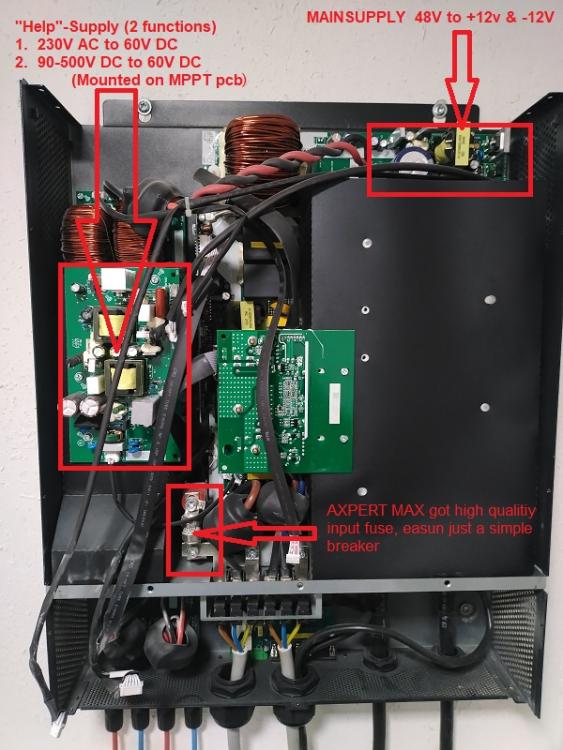
I disassembled my inverter today and did some measurements. Hope i got it right 😉. for testing i disconnct all plugs from help supply pcb and everything worked fine .....this made me suspicious then i made a few measurements: if only battery is available as power source this complete pcb is useless & main supply draws 0,45A from battery.(with 230V output active but no load it is 1,75A) if Grid is available the help pcb will provide 60V to main supply , battery is not used in this condition for feeding the logic if Solar is available Grid will be ignored but will also it provide 60V to main supply , battery is also not used in this condition for feeding the logic if you just pull off the SOLAR plug on help supply pcb then power comes from grid(if available) for all the logic (49w measured) (this could result in 50 watts being permanently drawn from the grid) it seems if you had a big battery (i got 1250AH 😉) it could make sense to disable the help pcb , and in this condion the "bug" to load battery with 2 amps when solar input is weak and grid is available makes now sence to prevent battery diacharge. (disadvantage is inverter starts only when button is pressend , if it runs already it stays on ) MPPT pcb there is a 12 wire connection to dsp pcb maybe this could be the folloing signals TEMP Heatsink TEMP of Air PV1 Voltage PV2 Voltage PV1 Current PV2 Current PWM signal MPPT 1 PWM signal MPPT 2 GND +12V from main supply -12V from main supply ??? named O/P on pcb


-
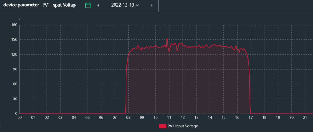
PV1 side west (only 4 trina 400w in series) I think this is what we all want to see😋 Gate drivers supply & Logic are independent of the power input of the pv inputs. But also i had to correct myself of the Firmware changes : Two changes are minimum to get it work,the subtraction value set to zero & the compare with 0,5A (value 50) set to 1 . I made an BETA Firmware based on 90.06 with just this two changes (named to 9007). (MPPT RANGE IS ORIGINAL 90-450V ) testet on EASUN & Axpert Max I 8KW @Coulomb i would be happy if you patch other files if there is a request . Reflash.zip