timematcher
Members
-
Joined
-
Last visited
Everything posted by timematcher
-
This another MPPT board that I found but it has a different shape and may not fit it./
-
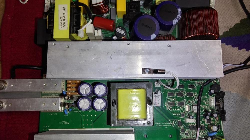
This is not an exact picture but the solar MPPT module for my Solar Inverter should look like this in order to fit in the Inverter. Focus on the metallic pins which fit in and get screwed in the corresponding long metal bars in the main PCB.
-
SCC 71-500605-XXG is what I need but not sure what XX should be? Serial Number? Where do i get the serial number?
-
I hope I am not too late to reply.. The inverter I have is actually a PWM Solar inverter. The PWM module is plug-n-Play. The PCB of PWM inverter and the PCB of the MPPT inverter is the same. The only difference is the PWM/MPPT module which can be removed easily. I was hoping i could replace the PWM module with an MPPT one. That is just a side note. I have not personally tested the following site, but I googled and found this service selling SCC boards. I do not want to post a link so I have taken high quality screenshots. Maybe you can use it and try to acquire the board if you are still looking for it and also share your experience with me here because I have searched heaven and earth for the SCC board for my Solar Inverter but haven't found it.. Let me know if it works out for you. Thanks
-
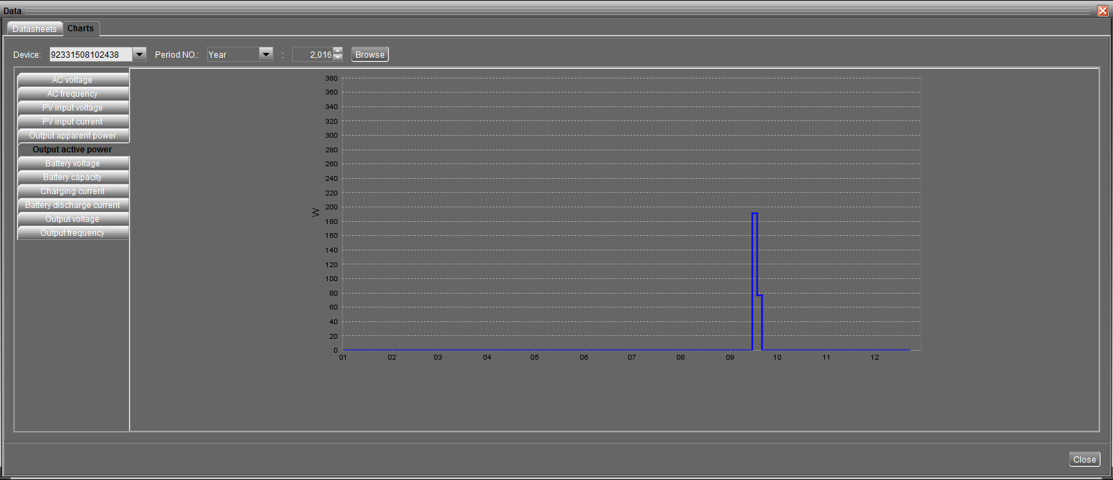
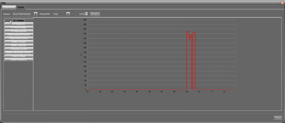
The cutoff voltage set in my Solar inverter was set to a high value (23.X volts). As a result, I would see 24.X volts on no-load and the inverter would cut off really quick in a few minutes before the voltage could actually go down 23.X volts... Also, i was adding load in small increments when testing that so I never figured out that battery had shorted cells and could not bear a certain load (beyond a certain threshold like a few hudnred watts ). Also, one has to open the caps on the two batteries and i was really proud that my batteries are brand new and I should not open their caps or something Haha It was only when i reduced the cutoff voltage to 21.X volts, i was able to reproduce the shorted-cell scenario and would see symptoms (bubbles on load) and voltage dropping sharply. I assisted the use of software (serial cable, software, windows) that came with my solar inverter and saw the sharp curve in the voltage graph of the voltage going down in minutes when load was only a few bulbs and a 1 ceiling fan (amounting to just a few hundred watts) on a 3.5KVA inverter with handsome-sized batteries (do not remember the amperage anymore but i have the same size custom-made batteries now and the same solar inverter).
-
When load is applied to the 12 volt battery (either through the Inverter/UPS or via a battery jerk tester) , following things start happening in a shorted cell: Lots of bubbles start coming out of the shorted cell(s) The overall voltage falls by the factor of each of the shorted cells. So if one cell is shorted , the faulty battery's overall voltage will fall down to 10 or 9Volts immediately while the other fully charged, non-faulty battery (in a 24 volt combination) will still show 12.xVolts on load and 13.x volts without load. If you have a single battery of 12 Volt , you can not do a comparison like above but you may see lots of bubbles coming out of one or more cells on load which would tell that particular cell is shorted. You can use carbon Rods (the one extracted from regular AA Cells), hold then with some metal clamper, and use a multimeter to test each cell by dipping the carbon rod(s) into each respective cell and comparing voltage between each cell. Please use this as last confirmation test and dip only for a short period of time as the sulphuric acid in the battery may start dissolving the carbon and introduce impurities in the battery. In an ideal fully charged, battery with no short, each cell may read 2.2Volts and the whole battery should read 13.x Volts without load. On Load, the battery should read 12.X volts overall, and each individual cell should read 2.1 or so volts. If you have a battery tester such as the following (shown in a screenshot), you do not have to perform the above steps but the above steps are more fine tuned way of testing the battery and specifically which cell is shorted. Hope it helps.
-
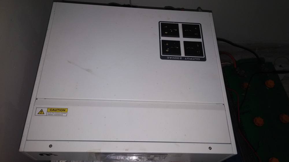
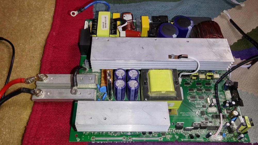
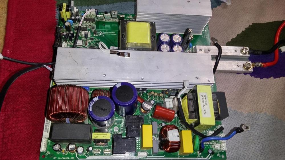
Hi Guys, Good day As per subject I need the actual picture of the MPPT board & part number of the "MPPT module" present in the ALFA-M3000-24 Solar Hybrid Inverter. The brand name is NS but it is very similar to Voltronic or Axpert models I have the picture of the board of the inverter with the missing MPPT module. I need the picture to procure the MPPT module. Please see attachment. Thanks

-
While we are at the topic, Can someone post a picture of MPPT Module for ALFA-M3000-24 please? I need to procure it but I do not have the MPPT module anymore. please note that I am requesting picture of the MPPT module of the M-series AFA-M3000-24. The real picture is needed so I can send it to my seller in China to procure it. Thanks so much.
-
@Mr T Here you go. Capacitor Details: 475K 350VAC See Photo 6.jpg Zoom it a little bit and you will find the value crystal clear. I hope I am not too late for the reply.

-
@Chris Hobson You are probably right. I should look for deep cycle batteries. They are available but much expensive.
-
@plonkster Thanks interesting finding @Chris Hobson @plonkster Its a 3-step charger so I understand the terms "Bulk Charging voltage" and "Floating charging voltage". Can you guys please explain to me a little bit the following terms to me? Back to discharge voltage Back to grid voltage Battery cut-off voltage Kind of confused about what these terms actually mean. My new settings look like this now: Do I also need to set battery type to Flooded or User? Thanks for your helpful response. Awais

-
@Chris Hobson @plonkster Thanks for your useful input. I think that is what I was looking for. I also think that the unit stops charging the batteries too quickly and switches to floating charge in about 10 minutes which is an incorrect behavior. I do not have any solar panels at the moment and I use only AC for charging. I will try the suggested Bulks settings as soon as AC grid comes back on. @Chris Hobson Phoenix is a catchy name, I think its all that is :). English although widely understood and used in our country, 90% truck drivers (who are the largest consumers of these batteries) are not literate enough to understand that! I think its easy on the tongue and seems a catchy name for most of those people. LOL
-
@Chris Hobson @plonkster @The Terrible Triplett I have these settings options. Please help me configure the right options for my batteries. The batteries spec is also attached.


-
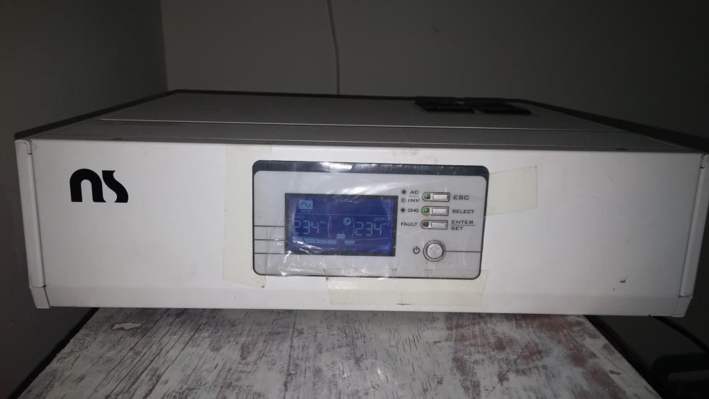
@Chris Hobson Yes I agree. Its probably a Voltronic clone. See attached images of the UPS. I don't discharge the batteries as I don't have any large load at the moment (2fans 60watt each and two tube lights 60watt max) . However, i think the UPS only float-charges the batteries and does not do a bulk charge long enough to provide them enough juice for the next load-shedding (which is one hour only). So after 3-4 load shedding(s) one hour each every 4 hours, decreases the juice of the batteries. If the batteries were being charged by the UPS (and no float-charged) this would not have been the case. If I could set the battery to user, what should be correct settings for the batteries? Please see attached images and advise Awais


-
Hi guys. Problem: The UPS seems to charge the batteries too quickly. Detail: This is a 3KVA Alfa P-3000/24 UPS with two 12Volt DC batteries (a total of 24 volts). If batteries are discharged to 30-35% (on load voltage 20.x Volts, UPS reading 22.26Volts), it seems to charge the batteries in almost about 10 minutes (voltmeter:24.5 Volts, UPS reading: 27.xVolts) Batteries are "Lead Acid water maintainable batteries" but the settings in the UPS are for AGM as default. I dont understand the difference and need advice. The only other options are Flooded or User. Questions/Suspicion: Obviously this cannot be right. Furthermore, even after having the batteries on AC charge via the UPS for more than 4 hours, each subsequent backup keeps on reducing until I need to charge the batteries using a separate battery charger or having them recharged by a battery guy. I want to understand what is wrong and whether its the settings that need to corrected or something else? I recently installed fresh batteries since I have was having problems with the previous ones. Background: I had problem with previous batteries when my UPS experienced a short circuit and needed to be repaired. After repair, It was found that cells of both of my batteries were shorted. So i installed new batteries and since then I am facing the problem as described above. Screenshots: I have attached the screenshots from WatchPower (the software that comes with CD) Kindly help resolve the issue and help me make/implment the right software/hardware solution. Awais


-
Thank for your reply @plonkster. Really appreciate the detailed explanation. I am trying to establish if its a fault in UPS or battery so that I can fix that problem. Right now I am unsure as to what exactly is problematic. Personally, in my humble opinion, If the UPS thinks batter is charged, it will switch to floating charge... and if the battery has a problem, it will get charged (or at least appear) to get charged immediately, attaining a voltage level that puts the UPS into an illusion that battery is fully charged. I need a second expert opinion so that I can work towards a solution. Thanks
-
Question: How long should it take for 3kva ups to charge a 12V+12V batteries from 70% to 100%?
-
Turns out, one of the cells in one of the 12Voolt batteries was shorted. I have got that cell removed and a new one installed. Still testing. will upload and share the results. I just want to make sure that UPS is supplying correct amount of voltage and current and there is no other problem in the UPS itself.
-
Here are the screenshots 1. Datasheet 2. Device Parameters 3. Graphs for various stuff. Please take into consideration and help me establish the battery's health as well as the UPS health. Thanks Awais


-
One small problem is that the batteries are getting charged very quickly and are not giving a backup of more than 1 hour on: 1. 3 tube lights of 60 watt each 2. 2 ceiling fans of 60-100watts This was noticed after charging the batteries for 3 hours straight (note: floating charge because it charged the batteries to full in 30 minutes). Furthermore, batteries are getting charged on a floating voltage as the battery charge indicator is full. Its gets full in almost 30 minutes. Please note that I have lead acid batteries which are water-maintainable and I had them recharged by a battery guy on a higher current (They do this because they say that UPS is not capable to charge a dead battery, the charge must be at least 50 percent or higher for UPS to pick it up). Does this mean that batteries are faulty or does this mean that they were charged to full? The batteries details are: 1. Battery type is set to AGM in software 2. Battery Bulk charging maximum voltage set to 28.2 3. Max AC charging current : 30Amp 4. Battery : Phoenix XP 200 Plus which according to this chart http://phoenixbattery.com.pk/product.php is between 120AH to 150AH. 5. Battery voltage in series for two batteries (12VDC each) when charging: 25.2 - 26V (taken via digital multimeter) 6. Battery voltage in series for two batteries (12VDC each) when dis-charging after 3 hr charge : 24.2 V DC I need to help figure out if the batteries are faulty (they get charged and discharged too quickly?) Also, need to figure out if its the inverter problem so that I can figure it our myself or get it repaired whichever option is cheaper... Thanks Awais
-
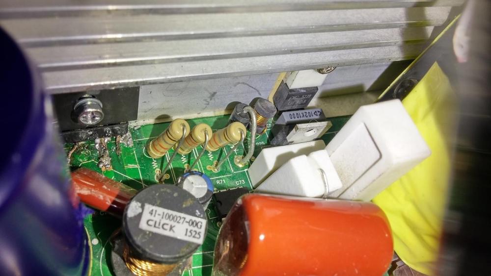
Hi I was not able to solve problem on my own but I reached out to a local repair shop who fixed the problem in an hour! LOL I wish I had gotten a hold of ALFA manual sooner maybe could have have saved me a couple of bucks LOL But this manual will surely come in handy when I run into another problem again. So thank you so much! The technician told me that two resistors were busted near the bridge rectifier. Further more, there was a diode busted in the output section and a couple of transistors in the output section on the heat sink. I am not sure If he was right about what he said (he could be exaggerating the problem to justify the money he took to solve the problem).
-
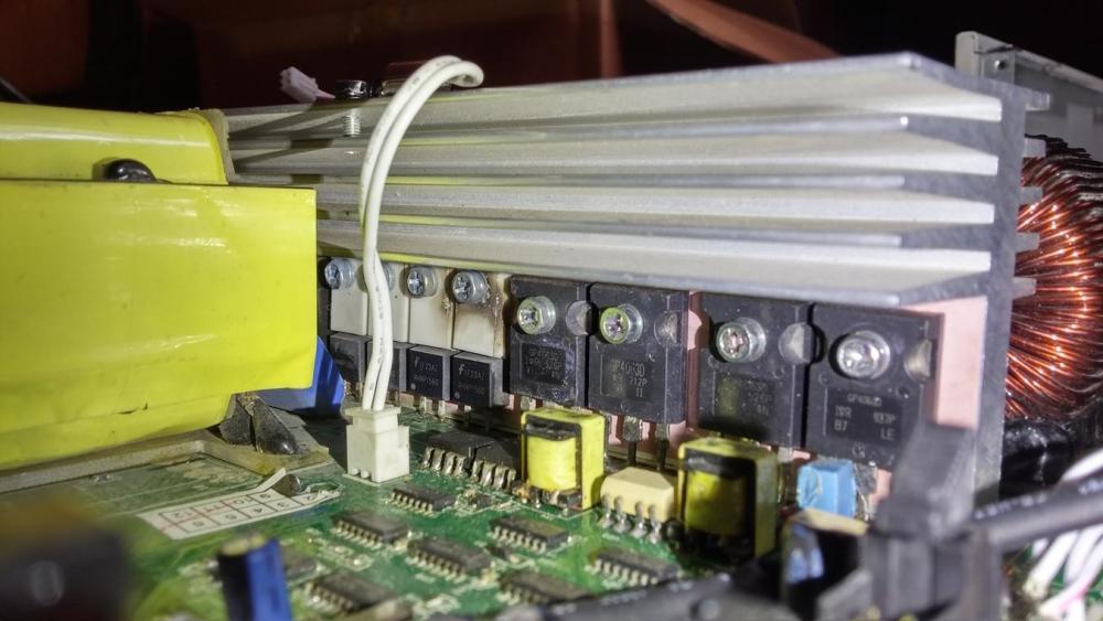
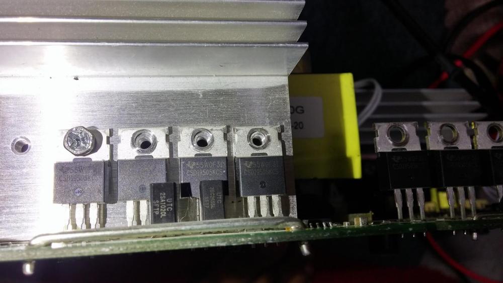
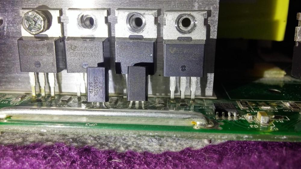
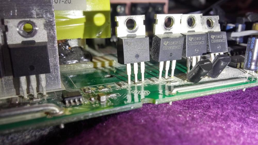
Hi guys So I was able to get all the major transistors, diodes and FETs except the fast diode UF808 and CSD1950KCS N channel Mosfet.. I need advice as to what process I follow further to investigate and fix the problem. Thanks Awais
-
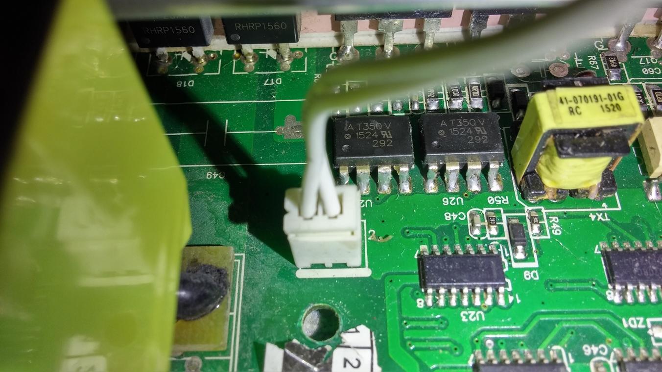
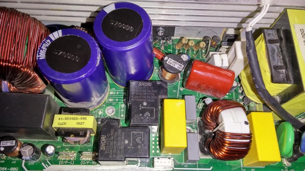
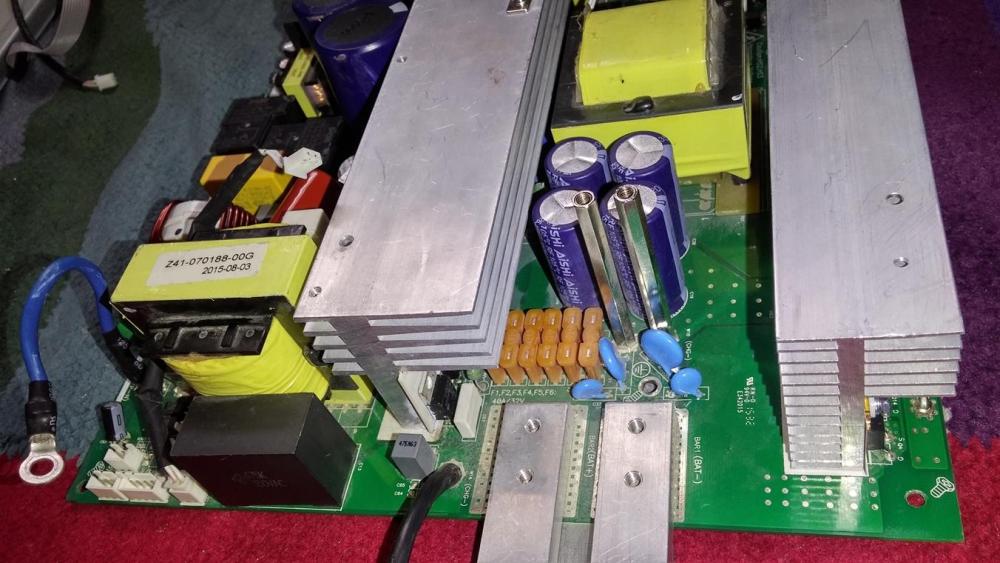
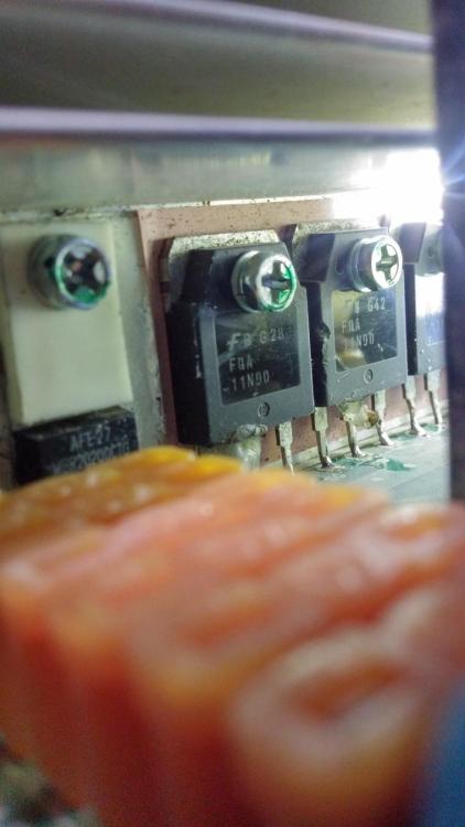
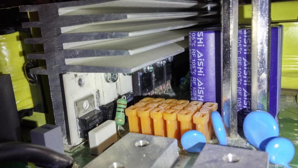
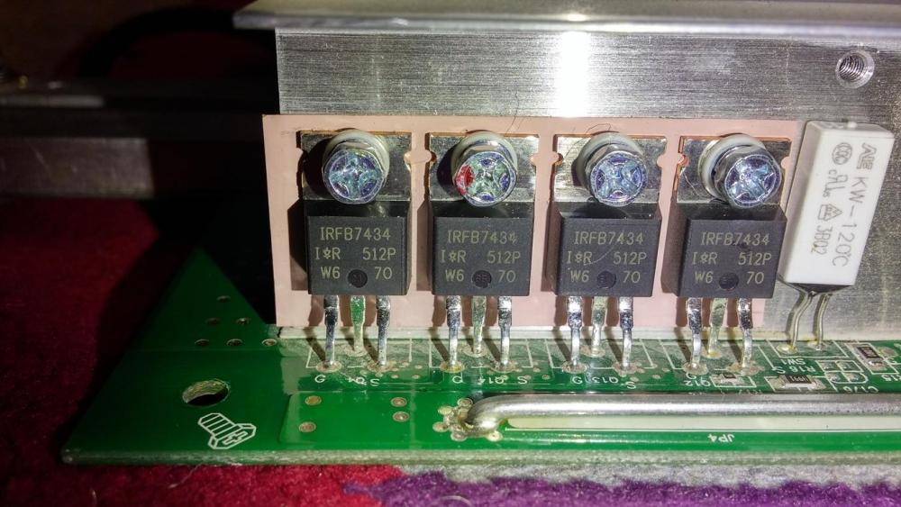
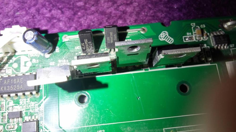
@Coulomb Thanks so much for the replies. Here are my findings so far: There are two UF808 diodes very close to the bridge rectifier. They seem to be reporting OK but I might procure and replace these if they are cheap enough. I found visible smoke carbon traces (indication of burning out) on two diodes both RHRP1560 (there are 4 of them but carbon was found on only two). There are 4 of them and I will get all 4. There are on the same sink at the back side of the bridge rectifier. Close vicinity. I am guessing the probably get shorted when voltage is applied as input. So I will probably replace them already. I found MosFETs GP4063D too. There are a total of 4 of them. I will probably take them all out and get them replaced too. There are on the same sink at the back side of the bridge rectifier. Close vicinity. DataSheet Here: GP4063D Data Sheet link The UC3483AN in close vicinity to the the bridge rectifier and the UF808 diodes. I consider these potential culprits and will replace them first during the course of my debugging. Here is a complete list of transistors , MosFets and Diodes MBR20200 qty 03 GP4063D qty 04 RHRP1560 qty 04 IRFB7434 Qty 04 CSD1950KCS qty 8 (these ones are further away from the main circuit and I am not sure if there are in the input portion or the output portion) The following 02 sets of transistors are in close vicinity to each set of 4 CSD1950KCS. 2SA1020L qty 02 and 2SC2655L qty 02 There are 03 MosFETS FQA11N90 in close vicinity of the bridge rectifier. UF808 qty 02 very close to bridge rectifier There are 02 AT350V ICS close to the MosFETs GP4063Ds (as mentioned before) Then there isour current controller IC UC3843AN very close to the bridge rectifier The other prominent components are a set of 02 470uf, 500V capacitors near the bridge rectifier. and then 04 4200uf, 35 Volt capacitors near the DC output terminals which I am guessing straighten the pulsating DC to pure DC for charging the batteries. I will go through the manuals in detail in my attempts to further investigate and fix the problem. I will post more updates. But i really appreciate your input if this paints any picture and gives any idea of what might be wrong. Awais Screenshots Please see attachments


-
Hi Guys, (Mods, please move it to the right section if i am in the wrong forum section). This post aims to request attention of those who have experience of repairing Inverters/UPS (especially Axpert/Voltronic etc) I am looking for the circuit digram for the following inverter Alfa P-3000/24. Its a 3kva Solar-enabled pure sine wave inverter from voltronic (but I have been using only Grid power). Voltronic Alfa P-3000 Product Url I had the un-lucky incident of having the grid's live wire and the output of UPS live wire touching together. As a result, the circuit in the inverter got shorted and as a primary victim, the bridge rectifier T6KB60 1N10B got shorted (at least that is the one i could Identify). So I took it out and put in a new rectifier but it got shorted again with a spark. At that time, the ground made common for both output and the input. So I removed the common ground wire and then put a new rectifier in again, This time, I put the UPS in series. Now both the "live" as well as the "ground" terminals of the output ports from the UPS were acting as if there are are one and the same and they have live even when the UPS is not turned on. I intend to track and troubleshoot the problem. This inverter is out of warranty now and there are very few people in the market who know how to repair it (I am having a bad luck trying to get some time slot as they claim to be burdened with other work). My understanding is : A rectifier in the output section (which is supposed to provide charging voltage to the batteries) gets shorted only when there is some other short component in near vicinity. The only closer component is current controller UC3483AN. There are other components such as resistors and diodes( I have checked all the diodes and they seem all right) and then there is the output section . I am looking for circuit diagram for this model Voltronic Off-grid Alfa P-3000/24 . This is locally branded as NS but internally its from voltronic power. Also, if there is a expert fellow, who is willing to help me troubleshoot the problem, I will greatly appreciate and welcome their useful comments. I can provide more details and screenshots if needed. Looking forward for the circuit diagram and any useful helpful comments from any expert in repairing or dealing with voltronic. Awais