timematcher
Members
-
Joined
-
Last visited
-
 Kilowatt Power reacted to a post in a topic:
Circuit diagram & Help needed repairing Alfa P-3000/24 Off-Grid Inverter
Kilowatt Power reacted to a post in a topic:
Circuit diagram & Help needed repairing Alfa P-3000/24 Off-Grid Inverter
-
This another MPPT board that I found but it has a different shape and may not fit it./
-
This is not an exact picture but the solar MPPT module for my Solar Inverter should look like this in order to fit in the Inverter. Focus on the metallic pins which fit in and get screwed in the corresponding long metal bars in the main PCB.
-
SCC 71-500605-XXG is what I need but not sure what XX should be? Serial Number? Where do i get the serial number?
-
I hope I am not too late to reply.. The inverter I have is actually a PWM Solar inverter. The PWM module is plug-n-Play. The PCB of PWM inverter and the PCB of the MPPT inverter is the same. The only difference is the PWM/MPPT module which can be removed easily. I was hoping i could replace the PWM module with an MPPT one. That is just a side note. I have not personally tested the following site, but I googled and found this service selling SCC boards. I do not want to post a link so I have taken high quality screenshots. Maybe you can use it and try to acquire the board if you are still looking for it and also share your experience with me here because I have searched heaven and earth for the SCC board for my Solar Inverter but haven't found it.. Let me know if it works out for you. Thanks
-
The cutoff voltage set in my Solar inverter was set to a high value (23.X volts). As a result, I would see 24.X volts on no-load and the inverter would cut off really quick in a few minutes before the voltage could actually go down 23.X volts... Also, i was adding load in small increments when testing that so I never figured out that battery had shorted cells and could not bear a certain load (beyond a certain threshold like a few hudnred watts ). Also, one has to open the caps on the two batteries and i was really proud that my batteries are brand new and I should not open their caps or something Haha It was only when i reduced the cutoff voltage to 21.X volts, i was able to reproduce the shorted-cell scenario and would see symptoms (bubbles on load) and voltage dropping sharply. I assisted the use of software (serial cable, software, windows) that came with my solar inverter and saw the sharp curve in the voltage graph of the voltage going down in minutes when load was only a few bulbs and a 1 ceiling fan (amounting to just a few hundred watts) on a 3.5KVA inverter with handsome-sized batteries (do not remember the amperage anymore but i have the same size custom-made batteries now and the same solar inverter).
-
When load is applied to the 12 volt battery (either through the Inverter/UPS or via a battery jerk tester) , following things start happening in a shorted cell: Lots of bubbles start coming out of the shorted cell(s) The overall voltage falls by the factor of each of the shorted cells. So if one cell is shorted , the faulty battery's overall voltage will fall down to 10 or 9Volts immediately while the other fully charged, non-faulty battery (in a 24 volt combination) will still show 12.xVolts on load and 13.x volts without load. If you have a single battery of 12 Volt , you can not do a comparison like above but you may see lots of bubbles coming out of one or more cells on load which would tell that particular cell is shorted. You can use carbon Rods (the one extracted from regular AA Cells), hold then with some metal clamper, and use a multimeter to test each cell by dipping the carbon rod(s) into each respective cell and comparing voltage between each cell. Please use this as last confirmation test and dip only for a short period of time as the sulphuric acid in the battery may start dissolving the carbon and introduce impurities in the battery. In an ideal fully charged, battery with no short, each cell may read 2.2Volts and the whole battery should read 13.x Volts without load. On Load, the battery should read 12.X volts overall, and each individual cell should read 2.1 or so volts. If you have a battery tester such as the following (shown in a screenshot), you do not have to perform the above steps but the above steps are more fine tuned way of testing the battery and specifically which cell is shorted. Hope it helps.
-
Hi Guys, Good day As per subject I need the actual picture of the MPPT board & part number of the "MPPT module" present in the ALFA-M3000-24 Solar Hybrid Inverter. The brand name is NS but it is very similar to Voltronic or Axpert models I have the picture of the board of the inverter with the missing MPPT module. I need the picture to procure the MPPT module. Please see attachment. Thanks

-
While we are at the topic, Can someone post a picture of MPPT Module for ALFA-M3000-24 please? I need to procure it but I do not have the MPPT module anymore. please note that I am requesting picture of the MPPT module of the M-series AFA-M3000-24. The real picture is needed so I can send it to my seller in China to procure it. Thanks so much.
-
@Mr T Here you go. Capacitor Details: 475K 350VAC See Photo 6.jpg Zoom it a little bit and you will find the value crystal clear. I hope I am not too late for the reply.

-
@Chris Hobson You are probably right. I should look for deep cycle batteries. They are available but much expensive.
-
-
-
-
-
-
-
-
-
@plonkster Thanks interesting finding @Chris Hobson @plonkster Its a 3-step charger so I understand the terms "Bulk Charging voltage" and "Floating charging voltage". Can you guys please explain to me a little bit the following terms to me? Back to discharge voltage Back to grid voltage Battery cut-off voltage Kind of confused about what these terms actually mean. My new settings look like this now: Do I also need to set battery type to Flooded or User? Thanks for your helpful response. Awais

-
@Chris Hobson @plonkster Thanks for your useful input. I think that is what I was looking for. I also think that the unit stops charging the batteries too quickly and switches to floating charge in about 10 minutes which is an incorrect behavior. I do not have any solar panels at the moment and I use only AC for charging. I will try the suggested Bulks settings as soon as AC grid comes back on. @Chris Hobson Phoenix is a catchy name, I think its all that is :). English although widely understood and used in our country, 90% truck drivers (who are the largest consumers of these batteries) are not literate enough to understand that! I think its easy on the tongue and seems a catchy name for most of those people. LOL
-
@Chris Hobson @plonkster @The Terrible Triplett I have these settings options. Please help me configure the right options for my batteries. The batteries spec is also attached.


-
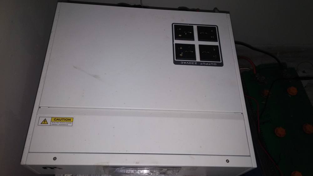
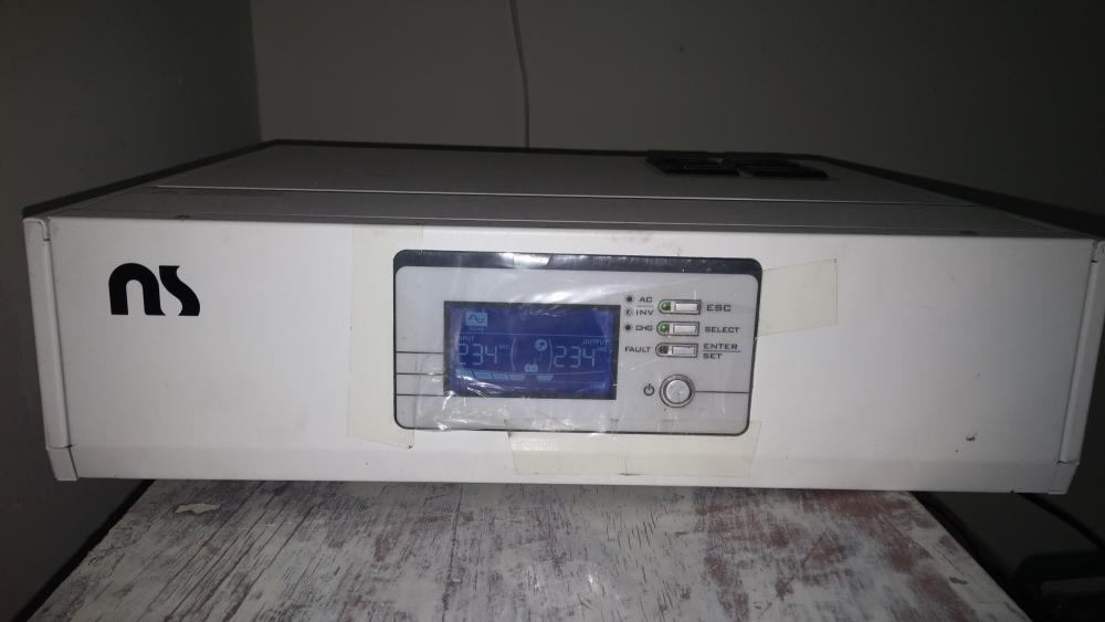
@Chris Hobson Yes I agree. Its probably a Voltronic clone. See attached images of the UPS. I don't discharge the batteries as I don't have any large load at the moment (2fans 60watt each and two tube lights 60watt max) . However, i think the UPS only float-charges the batteries and does not do a bulk charge long enough to provide them enough juice for the next load-shedding (which is one hour only). So after 3-4 load shedding(s) one hour each every 4 hours, decreases the juice of the batteries. If the batteries were being charged by the UPS (and no float-charged) this would not have been the case. If I could set the battery to user, what should be correct settings for the batteries? Please see attached images and advise Awais


-
Hi guys. Problem: The UPS seems to charge the batteries too quickly. Detail: This is a 3KVA Alfa P-3000/24 UPS with two 12Volt DC batteries (a total of 24 volts). If batteries are discharged to 30-35% (on load voltage 20.x Volts, UPS reading 22.26Volts), it seems to charge the batteries in almost about 10 minutes (voltmeter:24.5 Volts, UPS reading: 27.xVolts) Batteries are "Lead Acid water maintainable batteries" but the settings in the UPS are for AGM as default. I dont understand the difference and need advice. The only other options are Flooded or User. Questions/Suspicion: Obviously this cannot be right. Furthermore, even after having the batteries on AC charge via the UPS for more than 4 hours, each subsequent backup keeps on reducing until I need to charge the batteries using a separate battery charger or having them recharged by a battery guy. I want to understand what is wrong and whether its the settings that need to corrected or something else? I recently installed fresh batteries since I have was having problems with the previous ones. Background: I had problem with previous batteries when my UPS experienced a short circuit and needed to be repaired. After repair, It was found that cells of both of my batteries were shorted. So i installed new batteries and since then I am facing the problem as described above. Screenshots: I have attached the screenshots from WatchPower (the software that comes with CD) Kindly help resolve the issue and help me make/implment the right software/hardware solution. Awais