


Kilowatt Power
Members
-
Joined
-
Last visited
-
-
-
-
Hi all, I wanted to share our recent experience with a Deye firmware update that went wrong and how Deye support resolved it. Hopefully this helps someone in a similar situation. --- Date: 2026/04/28 Model: Deye SUN-8K-SG01LP1-EU --- 🔵 Original Firmware (Before Update) Protocol Version:V0.2.0.1 Lithium Battery Version Number:V0.0.0.0 HMI:VC.3.4.D MAIN_1:V3.8.8.1 MAIN_2:V0.7.1.7 --- 🔴 Failed Firmware Update - Resulted in COMM Error Protocol Version:V0.2.0.1 Lithium Battery Version Number:V0.0.0.0 MAIN:1400-0017 HMI:0000-C384 LCD Type:0000 What happened: Deye remotely pushed a firmware update from their end. After the update, the inverter displayed a persistent COMM error and would not recover. We followed the standard troubleshooting steps of switching off PV, AC and battery power, waiting 5-10 minutes then restarting but the error would not clear. We contacted Deye Support at [email protected] with the serial number, firmware details and photos of the LCD screen. They responded promptly and pushed a corrected firmware remotely. --- ✅ Latest Firmware - After COMM Error Resolution by Deye Support Protocol Version:V0.2.0.1 Lithium Battery Version Number:V0.0.0.0 MAIN:6027-1724 HMI:0000-C384 LCD Type:0000 --- The inverter is now back to normal operation. Full credit to the Deye support team for resolving this quickly. If you encounter a similar COMM error after a remote firmware update, my advice is: 1. Don't panic and don't replace the control board just yet. Check the forums first. 2. Contact Deye Support directly at [email protected] with your SN and firmware screenshots. 3. They can push a corrected firmware remotely to resolve the issue. Hope this helps someone!
-
Date: 2026/04/28 Model: Deye SUN-8K-SG01LP1-EU --- Original Firmware (Before Update) Protocol Version:V0.2.0.1 Lithium Battery Version Number:V0.0.0.0 HMI:VC.3.4.D MAIN_1:V3.8.8.1 MAIN_2:V0.7.1.7 --- Failed Firmware Update — Resulted in COMM Error Protocol Version:V0.2.0.1 Lithium Battery Version Number:V0.0.0.0 MAIN:1400-0017 HMI:0000-C384 LCD Type:0000 --- Latest Firmware — After COMM Error Resolution by Deye Support Protocol Version:V0.2.0.1 Lithium Battery Version Number:V0.0.0.0 MAIN:6027-1724 HMI:0000-C384 LCD Type:0000
-
 Kilowatt Power reacted to a post in a topic:
What is Inside My Inverter? (Comparing Different Off Grid 24v/48v Models)
Kilowatt Power reacted to a post in a topic:
What is Inside My Inverter? (Comparing Different Off Grid 24v/48v Models)
-
Kilowatt Power reacted to a post in a topic:
What is Inside My Inverter? (Comparing Different Off Grid 24v/48v Models)
-
Have a look at this British Standard covering fire safety for home battery storage installations that came into force on 31 March 2024. PAS 63100:2024: Electrical installations. Protection against fire of battery energy storage systems (BESS) for use in dwellings. PAS-63100-2024 - Protection Against Fire of Battery Energy Storage Systems.pdf
-
-
Kilowatt Power reacted to a post in a topic:
CT Installation For Site with Servo Stabilizer and Generator
-
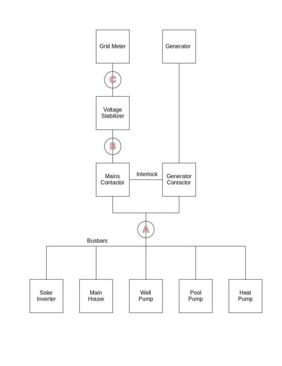
During a power outage, the standby DG set will automatically start and supply power to the busbars after a couple seconds i.e. mains contactor open and generator contactor closed. The external Chint DTSU666 smart meter will be powered through the busbars but CTs at position (B) will NOT read any current since the mains contactor open. Is it right to assume that the inverter will not push power back to the grid loads and generator alternator since the CTs at (B) will read zero current draw?
-
Kilowatt Power reacted to a post in a topic:
CT Installation For Site with Servo Stabilizer and Generator
-
Does anyone know the Deye RS485 ModBus RTU communication parameters (address, baud rate, parity, data bits & stop bits) for communication with an external CT meter? It's a pity that Deye does not provide an interface to change these basic parameters when enabling Advanced Function->EX_Meter For CT menu option for Zero Export to CT
-
A grid-tied inverter with storage is connected to a low voltage switchboard with stabilized mains supply and diesel generator power sources as shown below. Which is the most appropriate location for installing CTs for an external Chint DTSU666 smart meter for zero export management? (A) Between the change-over contactor and busbars (B) Before the automatic servo voltage stabilizer (C) Between the voltage stabilizer and utility meter I'm inclined towards position (A) with the only drawback being that the DG set could run on < 30% load during grid loss events.
-
Greetings, A site has 123/ABC (CW) phase rotation coming from utility. Wiring at the main incomer MCCB changes the phase sequence to 321/CBA (CCW) for the entire building. A 25kW grid-tie inverter with 25kWp solar synchronises to the 321 phase rotation after the main MCCB. It has been working for a little over a year off-setting between 40-60% of the total 12-20 kW daytime load. Is it worth swapping phases A & C at the bottom input of the main MCCB to match the grid phase rotation? This will definitely disturb the phase sequence already established for the two three-phase motors and passenger elevator.

-
-
-
Yes. 3 CT coils are installed with the same polarity on each phase. Had to change the direction of all 3 CT coils when I realised energy was being exported to the grid. Shall get pictures when I next visit the site.
-
-
-
 Kilowatt Power reacted to a post in a topic:
Panels generating 55% of capacity under ideal conditions
Kilowatt Power reacted to a post in a topic:
Panels generating 55% of capacity under ideal conditions
-
-
The 3-phase string inverter doesn't have the exact menu options as the hybrid but enabling unlimited export is still worth a try. I doubt if the utility meter will enter into tamper mode as a result. The worst that can happen is for the meter to count exported energy forward. The string inverter has options for a limiter or smart meter. Opted for the Eastron CT smart meter. Thanks. SUN-25K-G03 is a grid-tied inverter. Everything is on the grid side, after the main incomer MCCB.
-
Shall be able to share tomorrow's graphs now that WiFi is available in the basement.
-
The mounting structure is fixed. The 5° tilt angle was to allow for rain to naturally clean the panels. Having said that, I'll get the panels hosed down once again to completely eliminate the possibility of dust curtailing production. Wasn't measured. Shall try getting readings with the clamp meter thermocouple probe at high noon.
-
I stumbled upon an old Deye Inverter Catalogue with the below block diagram and efficiency curve for SUN-20/25K-G02 EDIT: Looks like 660Vdc is the sweet spot even though the MPPT operating range is specified as 200~850Vdc. I don't know if the formula Vdc = sqrt(2) x Vrms applies to the DC bus as is the case with rectifiers.

-
The 15kW load runs from 8am to 4pm. Maximum solar production is at 12 noon when the sun is directly overhead. North East happens to be the building azimuth angle. I would however want to believe that direction becomes less significant as the tilt angle approaches 0°. I read somewhere that a horizontal roof has a tilt angle of 0° and an azimuth angle of 0° I want to believe so. It's correctly displaying V, A, %THD, Hz, PF, kW, kVAr, kVA, kW and import/export kWh and kVArh. Most importantly it's communicating with the inverter and preventing grid feed-in. Shall peruse the manual once more and go through all settings just to be sure.
-
Kilowatt Power reacted to a post in a topic:
Panels generating 55% of capacity under ideal conditions
-
Or could the Grid Standard be throttling production? Which Grid Standard allows unlimited inverter power output for 240/415Vac distribution systems? The Grid Standard is currently set to IEC61727. Other available options are: INMETRO EN50549 EN50438 IEC61727 CUSTOM VDE_AR_N_4105 UTE_C15_712_1 RD_1699 CEI_0_21 G98_G99 AS4777 NBT-32004 AS4777.2 Australia A AS4777.2 Australia B AS4777.2 Australia C AS4777.2 New Zealand MEA PEA Norway Switzerland R25
-
Greetings, I'm trying to figure out what could be encumbering production of a grid-tied installation very near the equator. The maximum power generated under a clear blue sky is 8.5kW (55% of capacity) against a variable torque motor load of 15kW driven by a 18.5kW VFD at 50Hz. The balance 5.5-6.5kW required is purchased from the grid. Particulars of the Installation Inverter - Deye SUN-25K-G03 three-phase string inverter with 2 MPPT trackers running the latest firmware Panels - 14s1p Jinko JKM555M-72HL4 modules (7.77kWp, 696Voc, 574Vmp) on each MPPT, totaling 15.54kWp Orientation - 5 degrees tilt angle from the horizontal, 45 degrees East clockwise from magnetic north Cable run - 60m 4sq.mm PV1-F cable from the furthest panel on the rooftop to the inverter in the basement There's an Eastron SDM630MCT 3-phase RS485 Modbus RTU smart meter installed for zero export management The DC voltage displayed on the inverter when the motor is off is roughly 675Vdc which then drops to around 600Vdc when the motor is running. Would increasing the string voltage to 745.8Voc and 614.85Vmp by adding a panel to each string (15s1p) improve the overall efficiency? The maximum DC input voltage of the inverter is 1000Vdc.


