


Jannick
Members
-
Joined
-
Last visited
-
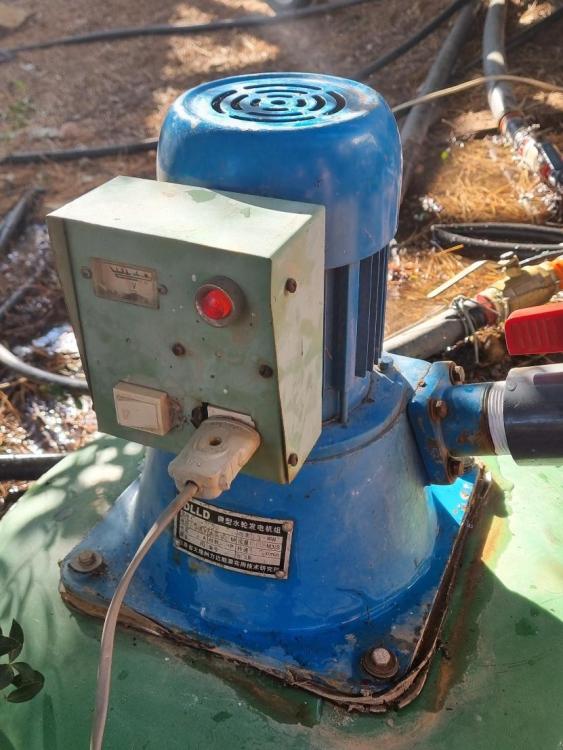
Fast forward 2 months on the Hydro Project: 14 kW generated constantly on two hydro sites! Key Findings: Feeding Rectified DC into Inverters: It is possible to feed rectified DC into a grid-tied/hybrid solar inverter. [See screenshot below of Fronius output power] Fronius Inverters: These work best for larger motors (>2 kW). You can set a fixed MPPT voltage for maximum power (500V in my case) and switch off one of the MPPTs to parallel them if higher amperage input is required. Heat Management: Rectifiers can generate a lot of heat, so appropriate heatsinks and cooling fans are needed for larger setups. Overvoltage Protection: Crucial to prevent damage to the inverter, capacitors and rectifier. Automatic Control Valves: These can control motor RPM and output power, simply built using using linear actuators and butterfly valves. Smart switches and power meters (e.g., SONOFF or TUYA) can be programmed for remote control of the generator and to prevent runaway scenarios. Grid Fluctuations: Minor fluctuations in grid voltage/frequency can cause inverters to stop producing power unexpectedly, causing the motor to spin at runaway speeds and generate damaging high voltage. A contactor installed between the motor and rectifier, controlled by a smart power meter, proved effective in protecting the rectifier and inverter against immediate high voltage before the automatic closure of the butterfly valve. This scenario happened at least once a day at one of our hydro sites, requiring a manual restart. This led us to explore alternative methods of feeding hydro power into our microgrid without the need for grid-tie inverters. Research: Overspeeding an Induction Motor to Generate Power: Basic Principle: Induction Motor: Normally operates below synchronous speed, converting electrical energy into mechanical energy. Induction Generator: When the rotor is driven above synchronous speed, the motor starts generating electrical power instead of consuming it. How It Works: Synchronous Speed: The speed at which the magnetic field rotates, determined by the supply frequency and the number of poles in the motor. Rotor Speed: When the rotor speed exceeds the synchronous speed, the direction of the induced electromotive force (EMF) in the rotor reverses. Power Generation: The reversed EMF causes the rotor to generate electrical power, which is fed back into the electrical grid or used locally. Link - https://electricalworkbook.com/induction-generator/ Our Current Setup: Direct Connection: The pumps are directly connected to our microgrid, without the need for rectifiers, capacitors, and inverters. Reverse Wiring: The pumps are wired to run in reverse instead of in the pumping direction. Protection Devices: Over/undervoltage and phase failure devices are installed between the motor and AC. Automatic Control Valves: These allow remote closure and opening of the water inlet, also preventing overspeeding of the turbine during grid failure. Smart Power Meters: Installed to monitor output power, voltage, and frequency (e.g., Sonoff Ring). Startup Procedure: Open the butterfly valve until motor RPM reaches slightly below synchronous speed (1400 RPM in my case). Switch on the contactor and allow the pump to run as a motor, drawing power from the grid. Slowly open the butterfly valve and observe the increase in amperage produced until fully open. Shutdown Procedure: Slowly close the butterfly valve until amperage is near zero. Switch off the contactor to cut off the motor from the grid. Close the butterfly valve slowly until fully closed. As easy as that! I would’ve never thought micro hydro could be so simple. We have greatly increased our energy independence and eliminated the need for Eskom/utility during winter months. Next up is to replace the pumps with Pelton wheels for more power and to build another dam for pumped storage during summer months. I will keep you posted! Screenshot of Fronius inverter output power. Notice the dip in production due to hydro downtime caused by grid fluctuations, as described above. Power consumption without the hydro. Notice that it never goes below 10 kW. Our power consumption with 14 kW hydro installed. It even charged our batteries at night when consumption reduced to zero.


-
-
-
Using a 50A 1000V full wave bridge rectifier for AC-DC conversion, I connected two 45uF 440V capacitors in paralell on the DC side, including a light bulb and switch for discharge, then straight to one of the MPPT's of a SunnyBoy Tripower 12kW grid tie inverter. We opened the valves, and then.... EUREKA! It worked like a charm, producing way above what we expected it could. The peak power measured was 580W with the voltage staying around 250VDC (see attached image). The next step is to take our old Lister generator apart and fit the alternator to the old pump, and then, hopefully, produce anything between 8 - 10 kWp. I will keep you posted on the results!

-
Quick Update: I ran the 300w Pelton generator this morning with an output of +- 150V AC, which was about the same volts after rectification to DC. I then connected a 45uF 450V capacitor on the DC side, which pushed the voltage up to about 230VDC (see attached images). I still need to adjust the water pressure and pelton nozzle, to increase the volts. I only have one cap connected and no dump or discharge resistor. What do you think, should I throw it onto the MPPT and see what happens? Let me know your thoughts.


-
Hi @Scorp007, thank you for your comments! I will add this to my cart on Robofactory. What smoothing cap would you recommend for the abovementioned alternator? I've read that some inverters allow for greater DC ripple than others (i.e. Sunny Boy is more tolerant). My plan is to firstly test out the system using a smaller 300w pelton generator, which we've had for ages and used to run during loadshedding back in the day. I'm hoping that this wil help me choose the most suitable grid tie inverter. The hydro site is quite far away from our Hybrid inverters, so using the Deye is not an option. We constantly draw about 10kW+ on the farm, so overcharging the baterries is not an issue (see image). We also have multiple dump loads all connected with Sonoff devices, to regulate our power consumption (i.e. 22kw boiler, cold rooms, freezer rooms, ice machines, 25 geysers, etc...).

-
-
Good day everyone. We have successfully beat loadshedding during summer months, and can run the whole farm without eskom for months on end. Our setup: 8 x Deye hybrid 12kw 3ph inverters 48 x Shoto SDC-10 Box 5 1 x 10kw & 1 x 20kw grid tie inverters feeding into our microgrid My Problem: WINTER IS COMING! Possible solution:? Use excess irrigation water to run a Pump As Turbine, coupled to a 10kw single phase generator alternator (which is currently not in use and used to supply the main house using a lister diesel engine). Rectify that AC power to DC and feed it into the MPPT input of a separate 10 or 20kw Grid Tie inverter. That power can then be used to supply our base load through the night, which is a minimum of 10kw, reducing our baterry draw and hopefully the need for Eksdom. We have multiple different 3 phase grid tie inverters, not in use (ie. Goodwe, SunnyBoy, AE, MicroCare, Fronius Synmo, ...) The RPM of the pump reached a maximum of 3500 when we tested it last winter, however, there was no motor attached. Head is about 70m with a pipe diameter of 150mm PVC, so water supply is not an issue, as our dams are constantly overflowing in the winter. Let me know what your thoughts are. Can this be done? What rectifier should I use? Any other equipment needed?


