


Tonytex230
Members
-
Joined
-
Last visited
Everything posted by Tonytex230
-
Thanks Scoobs ... I will give him a call later and find out when he is getting stock.
-
Hi Gambit Yes ... I tried Modbus 1 & 2 also tried setting up the Inverter as Slave and Master with the same results.
-
Hi Scoobs I see there are 3 option on the website Is this the correct one to buy: https://smarthomeintegrations.co.za/product/smartdeyedonglev4-international-shipment-self-flash-firmware-bundle/
-
A big thank you to all that has tried to help. However I have not managed to come right. I have tried the new RS485 module purchased from Communica. https://www.communica.co.za/products/wvs-rs485-3-3v-breakout-module I did change the supply voltage to 3.3V to the module. I have also tried running Pin 3 from Inverter RS485 Port to GND on ESP32 ... read somewhere that it is advisable in case there is no common GND. The part that I have a question about is this, when reloading the code to the ESP32 I get " Modbus device=1 set offline" as per below extract ? Any Ideas if this is correct or how do I get this to go online ?

-
I tried the pin change ... did not work. I will go past Communica tomorrow and get some RS485 boards. I will let you know how it goes.
-
Thanks Hilt I will try changing pins ... will also try Gambits sugggestion and go Past Communica to get some of the sugested RS485 TTL boards.
-
I know right nothing makes sense ... I have tried just a 1, I have tried a 0x01 and I have tried a 0x1 And when I look at the boot up logs they all show it as 0x01. I have tried all posibilties and get the same result 🤬
-
If i measure the voltage across Vin and GND on the ESP32 I get 5.1V ... is this correct ?

-
I am using a 5v TTL to RS485 module ... I got 2 sets on from Comunica and one from Micro Robotics ... This may very well be my problem ... I will try source a 3.3v RS485 board.
-
When I measure the A&B Pins while the ESP32 is powered up and connected I get 3.8 V
-
I tried pins 7&8 and still no luck. I also measured the voltage from the inverter on Pins 1&2 and 7&8 and on both sets I get 2.2 volts.
-
Thank you Hilt_Ctn I will give it a try and revert back ... At this point nothing makes sense and I am willing to try anything. The diagram you attached was the exact same diagram I used to wire up my ESP32. The only thing I don't know is if my RS485 port on my Inverter is maybe blown ???
-
I am using the RS485 port

-
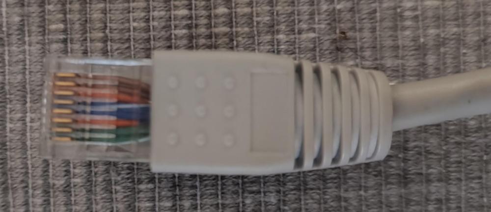
Hi Gambit Thank you for your reply. I have tried 2 different RS485 Boards one with R7 and the other without the R7 resistor. Also tried another LoLin ESP32 board but that didn't work either. I have also tried Bridging Pins 1&8 and 2&7 as per the Picture attached. Here are Pics of my ESP32


-
A Big thank you to all that put effort into this chanel. I have been banging my head for the last week and just can't seem to get my ESP32 to read from the inverter. I have a Sunsynk 8kw Inverter and am using a ESP32 WRoom-32 (Using Pins 16,17 and 4) with a RS485 adaptor connected to Pins 1 & 2 on the ethernet port. Inverter is set to Slave on Modbus 1. I have tried different Baud rates (9600, 19200 & 115200) I have tried changing Rx & TX pins. I have checked soldering all looks good. However I still cont get the ESP32 to get data from the Inverter. Below is my config file (simplified with just a few sensors) And the results I keep getting. I have tried another ESP32 board with the same results and I have tried with and without R7 installed on the RS485 Board. Any help in pointing me in the right direction would be greatly appreciated. ESP32 Config (Simplified).txt ESP32 Output.txt


