TTT
Members
-
Joined
-
Last visited
Everything posted by TTT
-
Added some photos. Also, 1-month update: it's been great. We've had more hot water than we've needed, and no grid power required, despite a few cloudy days. I am looking forward to it getting more interesting in winter, to be honest. However, I just ran into my first issue yesterday. With roof temperatures reaching above 40 C, the MPPT locked up. LCD just froze, showing 1000 W output, but there was no heating. Fortunately it came back on after toggling the DC isolator off and back on. But I am reconsidering placement. The MPPT is only rated to 45 C, so the attic is just not a suitable location, unless perhaps there's a fan and ducting for ventilation. Which is a schlep. In any case, a lockup requiring a power cycle is not the ideal response to overtemperature either, so it's good to know I guess. I have added ambient-overtemperature cut-out in software to pre-empt this more gracefully in the mean time.


-
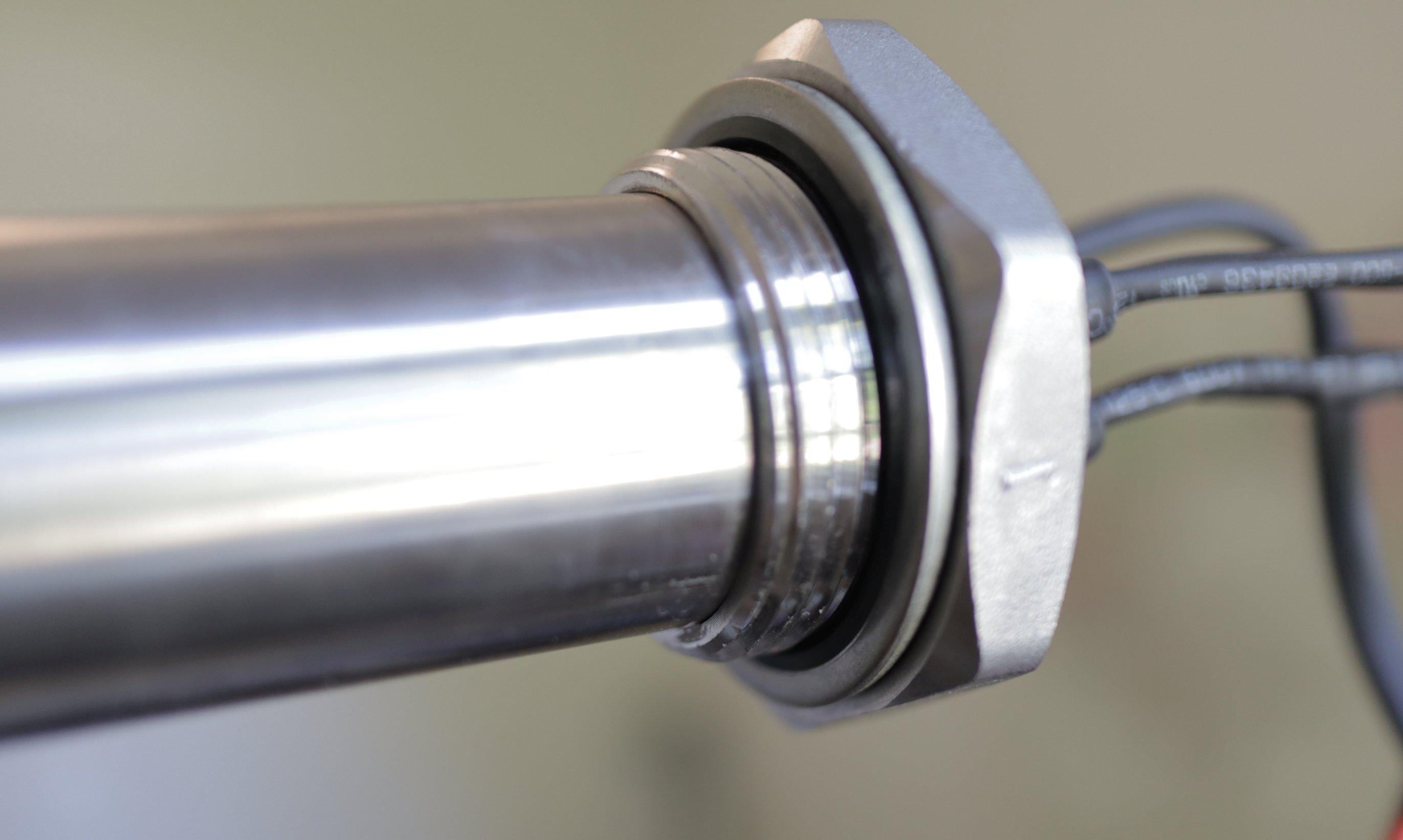
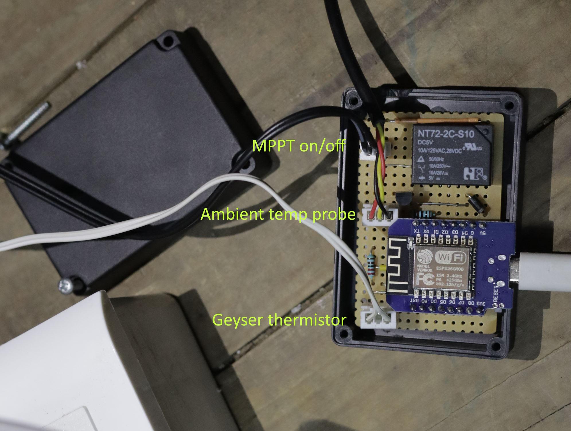
I've just installed a modified Geyserwise PV system. I thought I would post some of my findings, as it took a while for me to compile the information I needed. The objective was a solar PV retrofit to a standard Kwikot 150 L geyser, aiming for a payback period of 3-4 years. We use relatively little electricity (~270 kWh/month in summer, 420 in winter) so I wanted to keep overheads down to maximise ROI. A full Geyserwise install was going to come to about R 25k, but I went the DIY route and got it down to about R 12.5k in parts plus or minus some tools I'm sure I'll get to use again. 🤣 COMPONENTS 2x JA Solar 565 W panels on a north-facing IBR roof. Schletter ClampFit mounting hardware, end clamps and don't forget screws. Geyserwise 2 kW / 1100 W AC/DC PTC element (spec sheet), flange and "pocket". Geyserwise 72 V MPPT Custom controller based on ESP8266 (i.e. no Geyserwise TSE). Pre-existing CBI Astute in DB remains for AC switching. Existing thermostat for AC safety cut-out. MOUNTING I'm very happy with the Schletter ClampFit system. I went for it almost entirely on the basis that there is a short YouTube animation demonstrating the extremely simple installation procedure. Not having been up on my roof prior to this job, this was what I needed to have confidence I could do it myself. I think it's also a good fit for this kind of installation. With only two panels, and needing to have them separated by about a metre, any solution involving rails made no sense at all. Another thing I wasn't sure about was how manageable the panels would be. But one wife was sufficient. They are light enough that one person can raise a panel up while the other grabs and hauls over the edge. GEYSERWISE ELEMENT First impression: you could do some damage with this! It's bigger and heavier than expected. I was annoyed at having to replace an almost-new standard 3 kW element with this much more expensive PTC element but it's the key component in this system. It physically blends AC and DC power while keeping them electrically isolated. The wires look thin in the photos and even thinner in real life. The DC wires (blue/white) are only 14 AWG or ~2.5mm². Weirdly, the AC wires are slightly thicker at 13 AWG. The spec does not list rated DC current. I assumed it would be 1100/72 = 15.3 A but it draws closer to 20 A, possibly only limited by the MPPT. So I remain a little concerned... I did not buy the Geyserwise AC "thermal cutout" because as far as I can tell this is just a thermostat with a fixed setpoint. I used my old geyser thermostat. One thing to note is that it was a tight fit in the tube/pocket and you're supposed to jam both the digital temperature sensor for the controller plus the 75-degree DC cut-out switch in there as well. I ended up clamping the latter to the back of the element instead. There is an integrated gasket/seal at the back of the element. I'm not sure it's designed for repeat use so I hope not to have to ever remove it from the flange. Since PTC is by definition non-linear I was expecting a significant drop-off in power output as the temperature rose, but in this range it seems to be fairly close to a straight line. I was pleased to find the AC output starts well above 2, closer to 2.5 kW in ~35 degree water. GEYSERWISE MPPT The MPPT was a bit of an unknown quantity. It has this spec on its label: Voc: 150 Vdc Max DC load voltage: 72 Vdc Max DC load current: 20 A MPPT efficiency: 99% It also looks suspiciously similar to this device sold in New Zealand, which has a bit more info. The potential-free / dry-contact input (labelled "remote") means it can be controlled with a simple switch or a relay. It comes with a cable to connect it to the controller, with a BH-A1D self-resetting normally-closed 75 C thermal switch, inline in series. In the event of loss of external control, this switch should open and force the MPPT off before the water starts boiling. It comes with a mounting bracket to maintain a gap behind the heatsink, and with some ferrules, which is a nice touch. I had a look inside and found no interesting clues as to manufacturer etc. Just a couple of large 105-degree-rated caps and a huge inductor. Unfortunately it does not seem to have (an obvious) serial port or aux power output, but I plan to investigate a bit more at a later stage. I would like to be able to draw 5 V parasitically for the controller. In full sun with the 1130 Wp of panels (and cold water) the MPPT reports something like: PV input: 67 V Output: 19.8 A at 56 V (1108 W) That kind of current makes the DC element wires warm to the touch. The heatsink also gets quite hot. I measured 25 degC above ambient. I did see a thermistor when I looked inside so I'm sure it is safely thermally limited. It might not be quite 99% efficient but it's not far off. The absence of a fan is a good thing from a dust perspective. CONTROLLER I already have a CBI Astute in the DB to control the geyser's AC input, with some custom home automation scripts handling the timing. So I suspected the TSE1 was going to be mostly redundant. But I did need a way to monitor water temperature and of course to switch the MPPT. I put together a simple controller based around the ESP8266 (in a WeMos D1 Mini) that listens for an enable signal and setpoint over WiFi, and then acts as a digital thermostat, switching a relay connected via the supplied cable to the MPPT. The sensor itself is just a thermistor. IMPRESSIONS If the model and the MPPT hold up I'm fairly confident the 3-4 year payback is possible. Of course much depends on performance in more marginal conditions, so we'll see. I'm also pretty sure quicker payback is possible with a different design. In particular I'm still not convinced the monolithic element nor the PTC technology are required; two separate resistive elements would surely suffice. There's also no reason the MPPT couldn't be 3 times cheaper.


-
Yes. That does not mean there's an inverter inside. It just means it can pass AC through i.e. it contains "some sort of AC/DC changeover switch" as I referred to in my original post. But there is no indication what the DC-to-AC switchover point is. What does "insufficient" actually mean? Does anyone have one to confirm?
-
What product are you talking about? If this one then there's no indication it has an inverter at all, much less a grid-tied one.
-
But at what point does it switch? If PV is down to 100 W is that the total output to the element? I doubt it blends. Ideally I'd want it be able to control the changeover so I could put it on grid even when solar is still available, say because it's late afternoon already and temperature is still well below setpoint. So this product may be too simple. If it were some sort of DC-AC changeover / contactor switch I would control it electronically. I would take the thermostat out of the loop as well to avoid arcing. Of course I would substitute my own temperature sensing and control and would have to satisfy myself that it were safe enough. But it shouldn't be a matter of more than a couple grand in parts.
-
Thanks, this is definitely better. How does it avoid the thermostat welding closed? As an MPPT I'm guessing the output is chopped up (so effectively AC)? Also how does one configure this unit? What is the changeover point from solar to grid?
-
I've been looking at the economics of putting the geyser onto solar PV directly. I know an MPPT is required for high efficiency. What I'm not clear on is precisely the difference it makes. Geyserwise seems to be the most popular option, but the price is over R 7k including their PTC element before you even buy the panels. But with panel prices what they are now, if I just buy 4x ~400 W panels for R 5k, won't I be able to deliver about 800 W to my existing 3 kW / ~18 ohm element without needing an MPPT? Just some sort of AC/DC changeover switch? What am I missing? How is this not more economical than the Geyserwise?
-
This happens to us too. In our case I suspect it's an issue with municipal supply, because it only really happens in the evening peak regardless of our own draw. Something like a bad neutral out in the street. The clicking is presumably from relays in the UPS preparing to switch over to battery. So I believe the inverter is doing its job in response to supply irregularities, rather than being the cause of them.
-
I know I'm not the only one doing this but I haven't been able to find a good description of what the safety issues are. I have a portable inverter, 1 kW/1.2 kWh, and I've brought the lights circuit out of the DB, both L & N, and plugged it into the inverter. It works as expected, and I am pleased. I'm sure it's a code violation, uninsurable, etc. What I want to know is whether it also represents a real safety hazard in my specific situation, and how. The lights were not on the earth leakage breaker. They are all old plastic pendant/bayonet fixtures, no fans etc. I will be the only one changing bulbs. I will be reverting this setup when we move. In principle, I can't see why ceiling lights could not be treated like any other self-contained appliance that could be plugged into a portable inverter. Where is the connection or fault condition that I am not seeing that makes them unlike a freestanding appliance and that makes this unsafe?
-
There is definitely a shutdown-on-transfer problem with (some of?) these units. Can you reproduce it by switching off at the plug? If not I suspect it could be related to dynamics of how the grid ac goes down, e.g. brownout causing overcurrent trip. If so plugging the inverter into one of those fridge surge & undervoltage protector sockets could be a fix. Otherwise maybe send it back to have the SoC issue fixed and with any luck the shutdown bug is also resolved in new firmware.
-
There are a couple of photos at the MyBB thread: https://mybroadband.co.za/forum/threads/mecer-sol-i-bb-m1l-inverter-trolley.1218665/page-5#post-30603357
-
Did a full cycle fix this issue for you? I would probably err towards sending it back regardless as it sounds like you might have the buggy firmware, and that fan issue doesn't sound good either. QA on these units is definitely not their selling point...
-
Good to hear. The "device" seems to be doing the trick. And it's nice to know the product is being actively supported. (I do still wish we could get more info on the serial interface because I'm sure there's a lot of potential to DIY this thing.) I doubt battery life is affected much either way but it also can't do any good to charge faster than needed. At best there will be more heat dissipation.
-
Ignore the flashing indicator; if you monitor the power into the device you will see it does stop charging when it reaches charge termination voltage. This is probably why it stalls showing < 100% on the display in the first place: the battery reaches "full" and stops taking charge. Now the charge integrator no longer sees current flow, so it just stops incrementing, regardless of the % it counted to. In your laptop, at this point the SoC display would jump to 100% and you'd not notice it skipped a % or 5. Such a simple fix...
-
Regardless of what various support people say, I am 99% sure there is no hardware damage or defect, just a charge monitoring & display issue in software. The fix may well be no more than to set new calibration coefficients in EEPROM via some hidden menu. (It would be great if an OEM rep would post the procedure here!) The underlying charge (and discharge) cutout is based on voltage regardless of displayed SoC. When it runs at "0%" this does not mean it's over-discharging the batteries. Conversely when it hits "100%" it has not necessarily finished charging. Unfortunately battery voltage isn't displayed anywhere. So you'll have to take my word for it unless you're willing to open your unit up and monitor it yourself.
-
👍 That does sound worse than having no indicated SoC at all. I would do a full-cycle capacity check now and then regardless of this issue. As a side effect it should reset the SoC display. But it'll also give you confidence there's nothing actually wrong with the battery. I was pleasantly surprised to discover almost exactly the rated 1280 Wh in mine, about 10 hours at 130 W. Should be double for the 2 kW unit. It'll be interesting to see how these batteries age.
-
How did it go?
-
I would also love to know. This is as close as I've got -- the fourth image down looks identical to the mainboard in the SOL-I-BB-M1L and I assume the Kool 1 kWh as well. From Foshan Kemapower. But no evidence they actually designed or manufacture the board, nevermind integrate the device. And I can't find any other version of this trolley so perhaps the overall design is for the SA market only.
-
This is great news. Why not post the update firmware binary and procedure here? You can distribute the work and hassle of actually patching the affected units... there do seem to be a lot of them.
-
As far as I can tell the display indicating charging and the display indicating < 100% are connected. They are a display issue only. In fact the system is always keeping the battery at its max voltage. Indeed if you plug it into a power meter you can see spikes into hundreds of W draw every hour for a few seconds at a time. Presumably it attempts to top up the already-charged batteries. (This is at 100% with no flashing charging indicator.) It's not going to damage the batteries as long as the internal max voltage is calibrated correctly... but you can only confirm that by opening it up and measuring.