ShaunCro
Members
-
Joined
-
Last visited
Everything posted by ShaunCro
-
FYI Came across the service manual randomly today while looking for a screen replacement. https://powerforum.co.za/files/file/203-blue-mountain-energy-3p-wp-15-twin-service-manual/ Hopefully it helps someone iout.
-
 BME-3P-WP-15 Twin 15Kw Hybrid Inverter Service manual. This should be relevant for the BME-3P-WP-12 as well. It will also cover the Infinisolar and other voltranic derivatives of the same model. I battled to find this, came across it randomly when looking at another board I need to replace on my unit, so hopefully this helps some one out down the road. For some reason when you search for this, it comes up with the 30Kw inverter made by infinisolar which doesn't appear to have any relevance to this unit, the components are vastly different.
 -
Looks like you were spot on Coulomb. Busy with the repair now. Thanks :-)
-
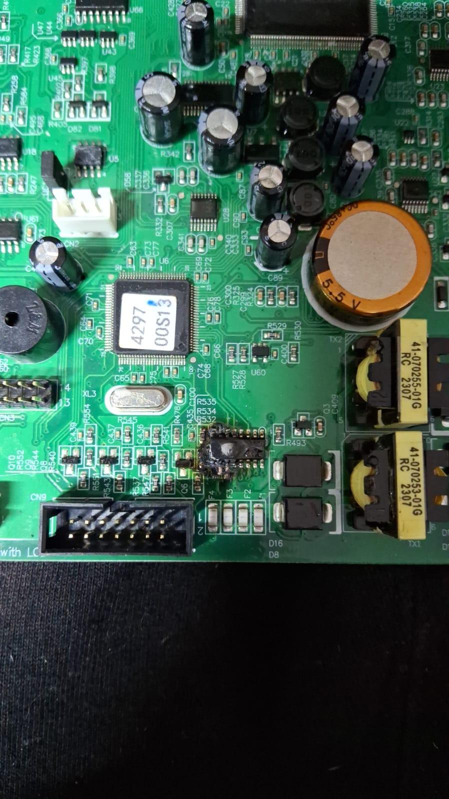
Yip, it is an infini licensed clone. I can find other versions of the service manual, but not for this particular range, the DC boards and Main boards as well as relay boards are very different to the manuals I've managed to find. And not so sure about it being a uln hey Coulomb, I thought that at first, but two of the pins terminate on the header leading to the com board, so I'm wondering if it's not some type of serial chip maybe? It's also very close to unpopulated LCD connector that isn't used from what I can see. There are also pins that terminate directly on the slave chip. But these could be power, I've managed to trace the points I need to run the repairs to, but it got late and I was tired and went to bed. Probably a good thing. I'll need to see what the slave chip is and pull up it's datasheet, and map out all the tracks to see. This control board appears to be used on a 10Kw, 20Kw and 30Kw system, with the latter two being free standing units, similar looking to old UPS's. Edit: I suspect this happened when I plugged the usb cable in, because my laptop went into protection mode, and I had to remove the battery and clear the caps to get it to start up again.
-
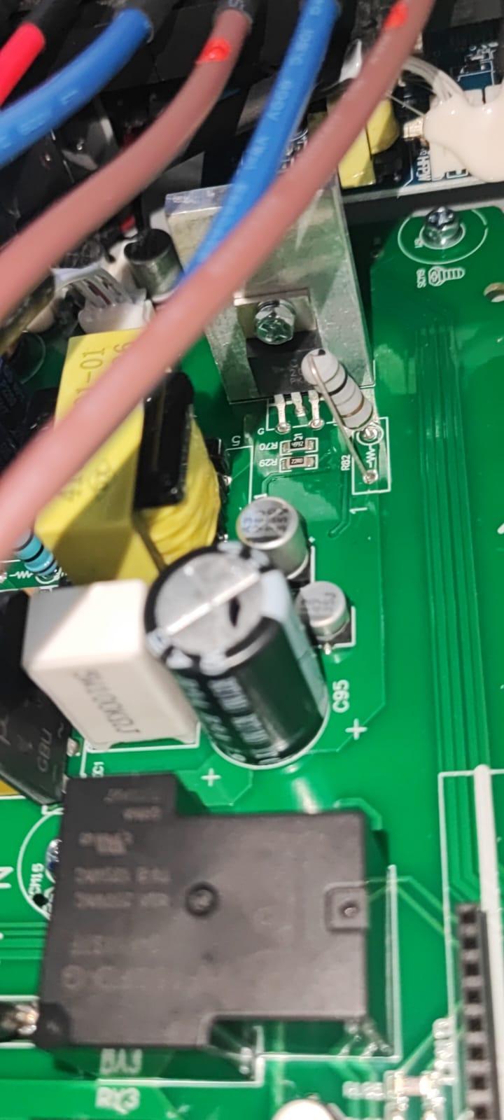
Don't you love it when it melts the copper into little beads... Oh well. Chip is unreadable, hope fully I can it somewhere.

-
So I guess, don't plug in a USB :-| Sigh. I wonder what chip that was now.
-
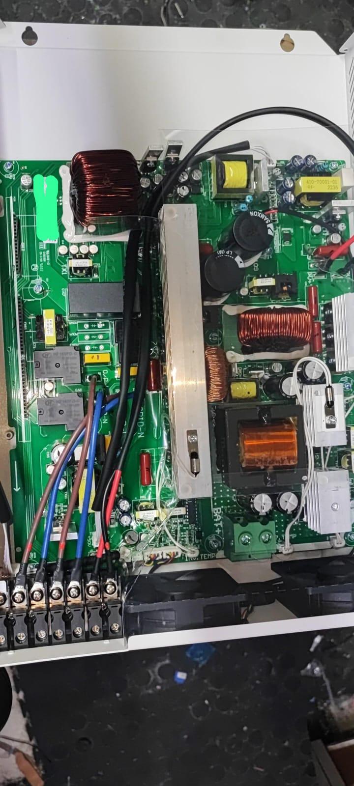
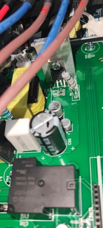
And my buddy says this was water damaged, on the DC battery board, there was lime build up, which he says happens when electronics take a swim and then try working after that. Which is strange, because it's meant to be IP65 rated, so who ever set it up, must have not closed it properly, and water got in. The unit came from CPT, and I remember there being floods recently or a few months back, but the entire left bank of mosfets on the dc board were cooked, and after removing that board the burnt electronics smell went away. We will play a bit more tonight and see if we can connect to the serial port and see what is there. I also picked up another 6 panels today, so I'll be running the unit on 2 strings on 10 x 550W panels. Which I believe is the recommended minimum. Everyone keeps asking if I have the space for all these panels, by my calculations I could easily fit another 15 after these 6, the joys of having a flat roof. The problem is just getting them onto the roof by myself, man it was a mission with the first 14 panels.
-
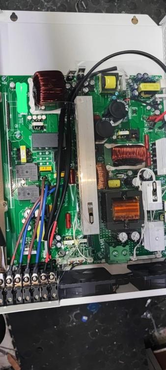
So a progress update on this. I replaced the DC board, and relay board, because the one I was supplied was different to the one I had in there. Much larger. I could only get the 12Kw dc battery board. And it appears that someone has tried to repair this unit before, because looking at the numbers on the boards, the Main board doesn't match with the rest of the boards fitted. When I say this, I mean that the old relay board and a few others ended with a 00G where the newer ones end with 01G. I also purchased another main board but after testing all the IGBT's on the board, it seems fine, and all tests on the other components seem fine in circuit, so will have to see. I hooked up a 51.2V battery to it last night, and hit the cold start button and fans started spinning and I could reach the built in wi-fi unit, but the battery was a bit flat, so it spent the night and day with a charger connected feeding it 6A and 53.5V it's almost done and then I'll try again. So, with last nights startup, the screen wouldn't come on. Now, when I received it, there was only 1 cable going from the Comm board to the screen, but I see another connector on the control board marked for LCD, and not sure if this, or another cable is missing. Hence me hoping someone has the service manual so I can check wiring for this type of thing. Mailed Segen on Monday with no reply. Mailed BME today, so will see if they reply. Otherwise just gonna have to guess I guess. 🤷♂️
-
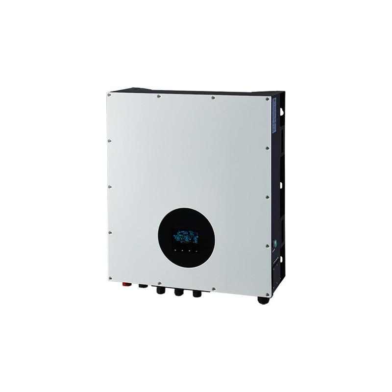
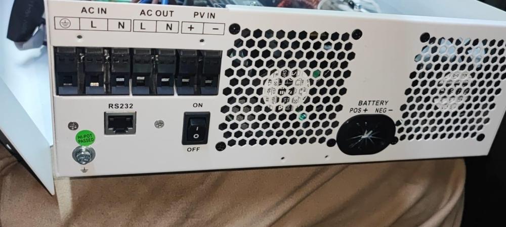
Morning All, So I bought the inverter mentioned in the title this weekend. It was an insurance recovery item, so got it pretty cheap. It's brand new, but does have a something blown, that we still trying to find. But, I was hoping someone perhaps had the service manual and the installers manual please? Myself and a friend (who has been repairing power electronics his entire career) are busy going through it, but was hoping there was a manual to make our lives a little easier. We connected up a 200Ah lifepo4 battery and it just beeped at us. I don't have 3 phase at home, so will probably take it to the wife's work this weekend to connect up and check it properly, or I'll need to put all 14 of my panels in series and see if that is enough to power it up. Why do I want it? All the best tools for the workshop are 3 phase. 😁 Specs: The BME WP TWIN 15kW is the latest commercial inverter from Blue Mountain Energy. The WP features offer a IP65 ingress protection which means the inverter is safe for outdoor use while the TWIN features offers dual outputs for smart load control. The BME WP TWIN hybrid solar inverter has on-grid and off-grid capabilities designed to keep businesses and/or residencies operational during power outages and reduce energy costs when connected to the grid. The BME 15kW has a range of features such as: 150% unbalanced load support - Allows for power to be share between phases Dual outputs for smart load control Parallel up to a total of 6 units - Total of 90kW power IP65 ingress protection – Safe for outdoor use Built in Wi-Fi for remote monitoring 5-year standard warranty The BME TWIN 15kW is NRS approved Weight: 78 kg Rated Power: 15,000 W Min PPT Voltage: 320 V Max PPT Voltage: 950 V DC Startup Voltage: 350 V DC Shutdown Voltage: 320 V Max Input Voltage: 1,000 V Max DC Power: 22,500 W Max AC Power (5 Minutes): 16,500 W Surge AC Power (1 Second): 28,500 W Max DC Current: 54 A Max DC Inputs: 4 Has DC Fuses: 0 Connector: MC4 Included Connectors: 4 Euro Efficiency: 95 % Transformer: None IP Rating: IP20 MPPT Quantity : 2 Has Integrated DC Switch: Yes Warranty: 5 years

-
Sorry @Youda didn't mean to hijack your thread, just popped up the most when I was searching the forum. Nice setup by the way. :-)
-
Thanks for the info Youda. I'll play around and see what is possible. Like I said, it was given to me, so didn't really have a choice as to the model, but the info does raise some interesting idea's that I'll explore. If need be, I'll grab a JK BMS and pop it in the box to run the cells. Just enjoying messing around and seeing what is possible with different hardware, and the solar stuff is fun and new to me. I need to ask though, do the newer Pylon's have current limiting yet? Because from what I have seen with this battery, it's nailing the batteries in the 3rd pack, on the negative side. And, a bit of googling and a couple youtube vids also show a similar thing. 3rd pack gets nailed first, one or more cells fail there, which leads to stress on the other cells through out the battery, and having to pick up the strain, they then start to follow suit. Seems like an issue that needs to be addressed, Also, I notice this was battery 1 in how ever many were installed in the cabinet. Which leads me to believe that it's taking the brunt of the charge, and most likely charging far too fast for these foil packed cells. This is not only the batteries fault, poor setup is also a big factor, and not enough knowledge on the matter. (Or just enough to be dangerous)
-
Hi Guys, I was given a Pylontech US2000 battery yesterday with swollen cells. I typically build my own batteries out of LifePO4 single 32700 cells, and was hoping that I could convert this one to a 24V setup opposed to the 52V setup it was originally configured for. Is it possible to change? Would just look so much neater than the crates I'm storing my batteries in at the moment. :-) Edit: Added pic of the unit.

-
@Wicard I did a bit more digging around this, but I sold my unit to purchase Revo units which supported parallel mode natively. But, it's not necessarily using RS232 and could be using modbus. I know there was a setting for the modbus node ID under the settings of the inverter. Unfortunately not much more I can do with out a unit around. :-(
-
Hey 3Chord, 9600 on the baud rate, solar assistant should be able to speak to it, just the Rx and tx pins really, pin 8 is ground, pin 4 is 5v. But after playing around on the JTAG pins and not having any joy, I thought best leave it alone in case I break it. Bought a hoselect unit, also 3.5, but isn't affected by the float bug in user mode, and has all the parallel boards in place already. If you need anything else shout, I may have come across it.
-
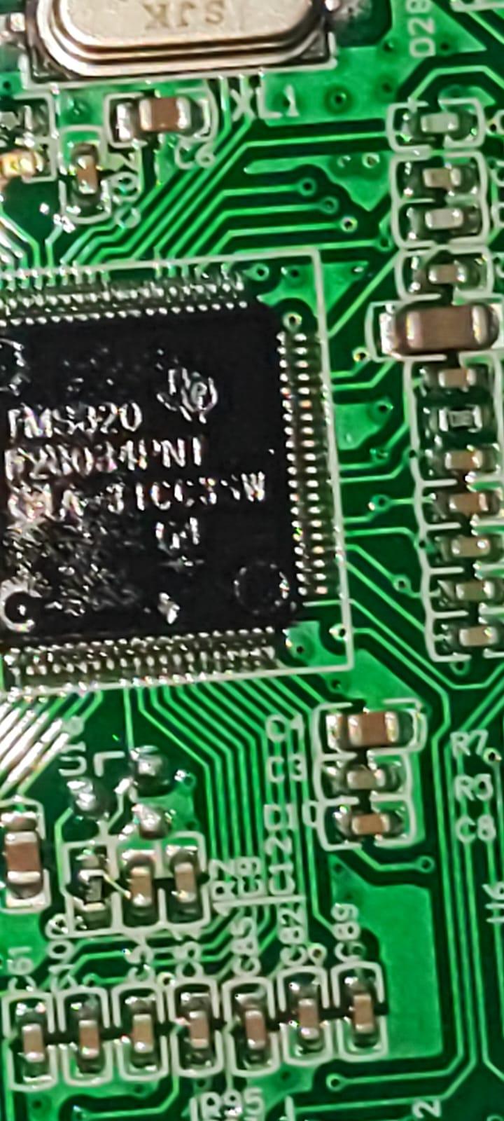
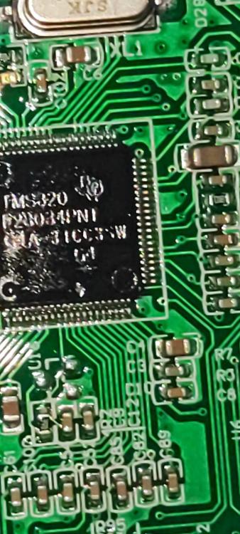
actually got the processor model wrong, Not a bad little thing, from the piccolo range for controlling high end brusless motors https://www.ti.com/product/TMS320F28034?keyMatch=TMS320F28034PNT&tisearch=search-everything&usecase=OPN-ALT#params So, actually have a lot of the tools already to talk to it, makes life a little easier I guess.
-
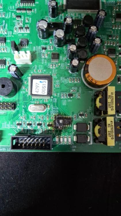
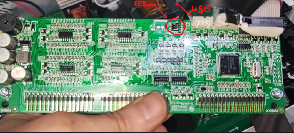
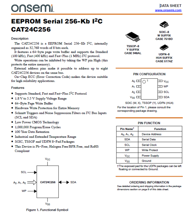
So, looks like we have Texas Instruments as the main processor in the newer version of the inverter. TMS320 Not the greatest around, clocking in at 40Mhz, but hey we used 8 bit chips for years in 3D Printing, so who am I to judge. 80-ns Instruction Cycle Time 544 Words of On-Chip Data RAM 4K Words of On-Chip Secure Program EPROM (TMS320E25) 4K Words of On-Chip Program ROM (TMS320C25) 128K Words of Data/Program Space 32-Bit ALU/Accumulator 16 × 16-Bit Multiplier With a 32-Bit Product Block Moves for Data/Program Management Repeat Instructions for Efficient Use of Program Space Serial Port for Direct Codec Interface Synchronization Input for Synchronous Multiprocessor Configurations Wait States for Communication to Slow Off-Chip Memories/Peripherals On-Chip Timer for Control Operations Single 5-V Supply Packaging: 68-Pin PGA, PLCC, and CER-QUAD 68-to-28 Pin Conversion Adapter Socket for EPROM Programming Commercial and Military Versions Available NMOS Technology: TMS32020 . . . 200-ns cycle time CMOS Technology: TMS320C25 . . . 100-ns cycle time TMS320E25 . . . 100-ns cycle time TMS320C25-50 . . . 80-ns cycle time Sorry, meant to be a pic of the RS232 Module, but too much in the way Controller board, you'll see the unpopulated USB header to the left of the large amount of "I said stay there" on the one connector, then there we have a 256kb eeprom chip just to the left of that and a CN2 that is missing it all. And of course JTAG to the right. Really battled to get a decent pic of the processor though, I hate the varnish they paint on, makes things difficult to photo. The blotch isn't a burn out by the way, just the coating. The EEPROM is an onsemni with a std i2c interface, never done it before, but always wanted to try, but lets see if I can pull the firmware off it in the morning. Then we can can see what is hiding away.
-
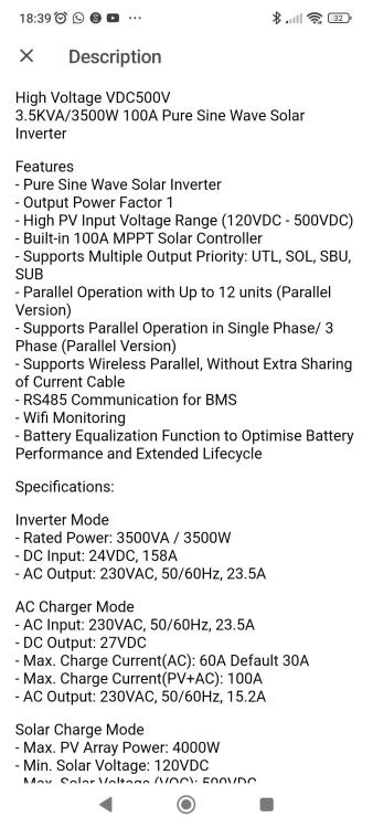
The marketing that was pretty much everywhere for this device is very misleading to. I see solar warehouse changed their write up for it as well, but this is what you typically read when looking through the specs.
-
Yeah, it's in the dessmonitor web front end but not in the actual options of the inverter, which means it would need a flash to support the option. And well, if I can't even find the hardware, I doubt the firmware will be any easier. But, I'm not one to give up easily, I'll keep up the hunt for the hell of it. 😄 Besides, I like a challenge. The previous versions were Axpert clones, before my original unit, and I have found versions of my version on Ali, but clone after clone after clone, so it's like a never ending rabbit hole.
-
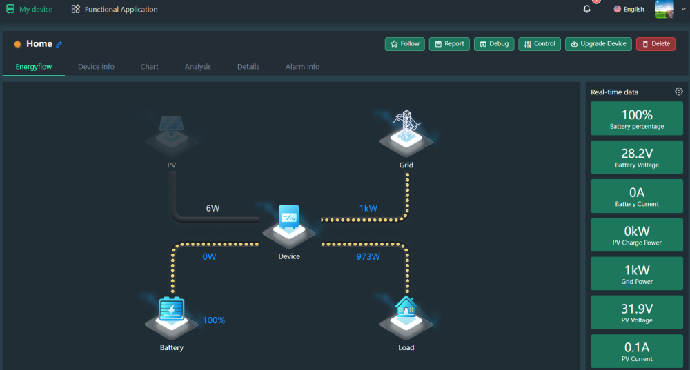
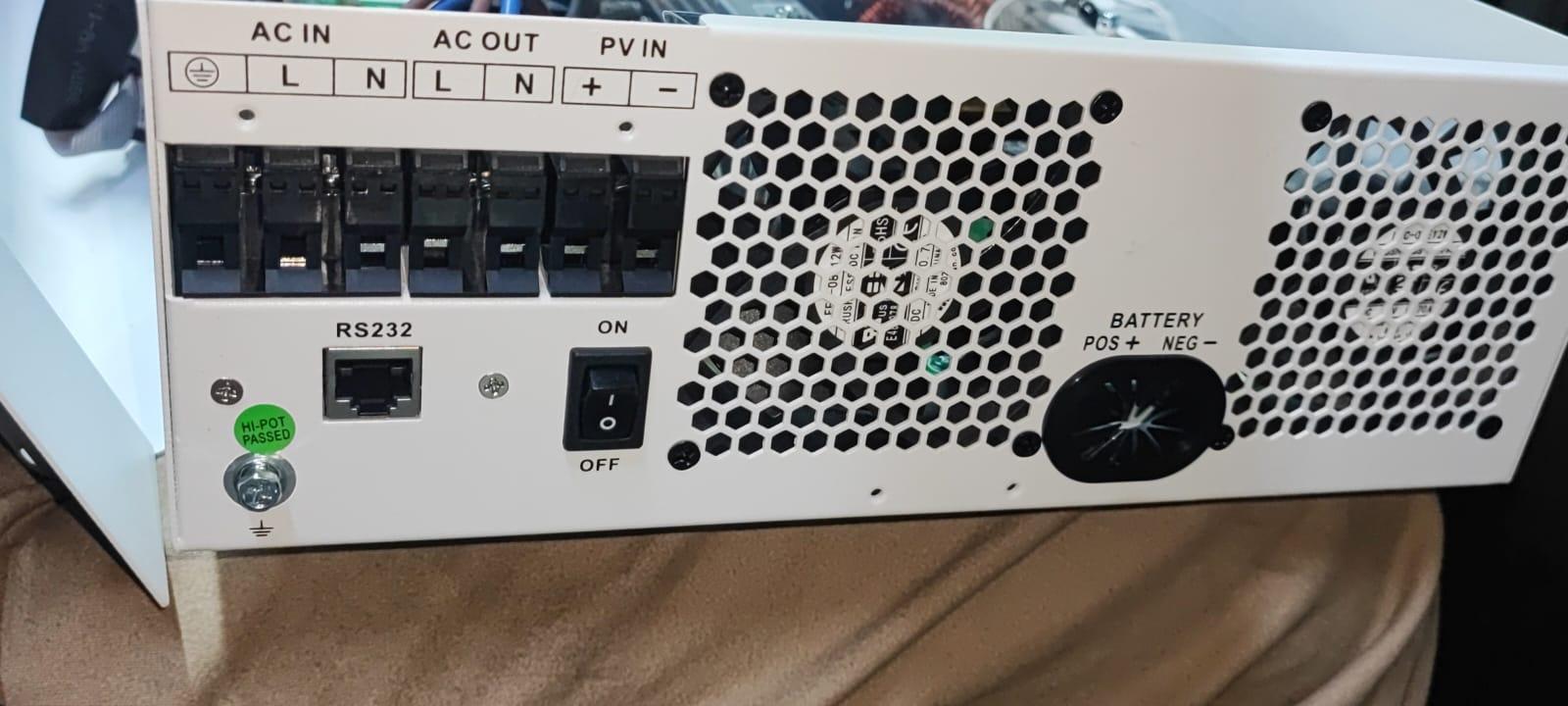
I have been meaning to play around there and try link it up to home assistant, but have been busy with work and other projects. Work finishes up today so I'll be playing around very soon. Right now it's connected up to the Wifi Pro dongle and I have been monitoring power usage etc via the dessmonitor, but find it a bit lacking. Still a lot I have to learn with this, so excuse my noobness. That interface is pretty much identical to mine, except for a minor difference in the icons, but the rest looks the same. But I'm pretty sure you are spot on with the pins though, typically with a DB9 the 5th pin (Green here) is ground, which goes to 8 on the RJ45, and pin9 is typically not used, but can be used for the Ringer function on older modems, so more than likely the 5V on pin 4 of the Rj45 (Black). To be honest, it looks more like a USB Serial with the + data data - layout. I recently purchased the newer version of this inverter, hoping to find a way to parallel them. Have ordered a generic dongle for the normal 5500 and 3500 60A version, so will be interesting to see the difference in pins. But have a feeling this will need to go into the workshop as a separate unit. Oh, in case you meant the printer type usb connector a lot of the units come with, this unit doesn't have that port. It only has the RJ45 RS232. Nothing else, though the controller card internally does have the functionality for it, it's just unpopulated.
-
Ah, thanks for that Coulomb, I learnt something new then. Reason I found anenji interesting as well was because of this statement on their site. But this seems to be a false hope. I'm starting to feel the inadequacy of my 3.5. And it's been a reliable stable unit, so would hate to have to get rid of it, so was hoping to parallel it some how. Pretty sure if they provided us the parallel card that the 5.5Kw Pro has it would work fine, but doubt we would be so lucky.

-
Hey Guys, First time I'm posting, but thought I would share since I haven't seen any post regarding the pin of the RS232 port on the Ecco HIN3500. A while back I contacted ECCO and requested the pin out or a compatible wifi dongle and they made up a cable for me that works with the SmartESS and Dessmonitor PC interface. It's pins are different as far as I know from the standard 5500 which you can get the dongle for, and for the newer 60A version. I have the previous version of the HIN3500 100A MPPT that looks like this. So, if it helps anyone, here we go. And the Dessmonitor screen that I get running off that cable with the wifi dongle they supplied: Also, I think I may have tracked down the manufacturer of most the inverters we have here in SA, Found mine there, Lux Power, Axpert, Kodak well what look like versions of them. www.anenji.cn