DM_UA
Members
-
Joined
-
Last visited
-
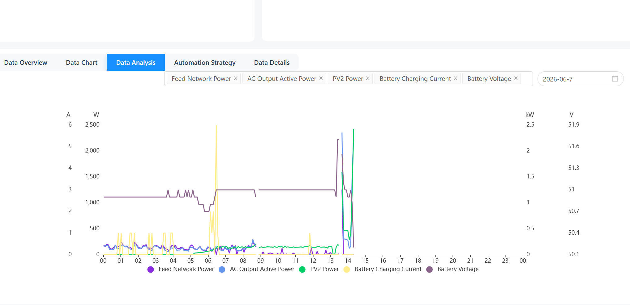
25.68 helped a bit. At first everything was fine, but then - again After flashing 25.68, initially everything was fine: - SBU mode, charging batteries from solar at 30A with no AC load — no problem - Connected AC output, 2.5 kW load, then disconnected — no problem - Pulsing load 1.4 kW (coffee machine, brewing a few espressos) — no problem However, as soon as battery charging occurred simultaneously with AC consumption — problems started and the same F17 High DC Offset fault appeared. More specifically: AC load was no more than 1.5 kW. Batteries had reached 100% SOC. PV output was insufficient to cover the load, so the inverter was drawing from the batteries. The fault occurred at the exact moment when the inverter switched from discharging the batteries to charging them from solar. Setup: - Inverter: Sunmart Ultra 11kW (Axpert Ultra) - Battery: 3 × 48V 100Ah LiFePO4 in parallel, 15S, user-defined battery type - Bulk: 51.7V, Float: 51.0V, Back to battery: 51.0V - DSP firmware: 25.68 - Mode: SBU - F17 High DC Offset fault happens specifically at the transition moment from battery discharge to solar charge, at 100% SOC, under AC load. Charging from AC has no problem. Maybe there might be some physical fault on the PV input side (condensers, drossels, etc)? I am attaching a chart from today (2026-06-07). The inverter was in SUB mode until 13:00. At 13:00 I flashed DSP 25.68 and switched to SBU mode. The fault occurred around 14:00 — visible as a sharp spike on all three parameters (PV2 Power, AC Output, Feed Network Power) followed by data cutoff when the inverter shut down due to F17. What I don't understand also why I have data on Feed Network Power chart, if feed to grid has been disabled?

-
-
Is this firmware made for Axpert Ultra 11Kw to fix F17 Fault?
-
-
-
Yes, the settings are missing. It's how it is. The wifi connection is for monitoring only. I have Solar Assistant and it's the only way to have the remote control with these models. Don't know why they limited that in Solar of Things app.
-
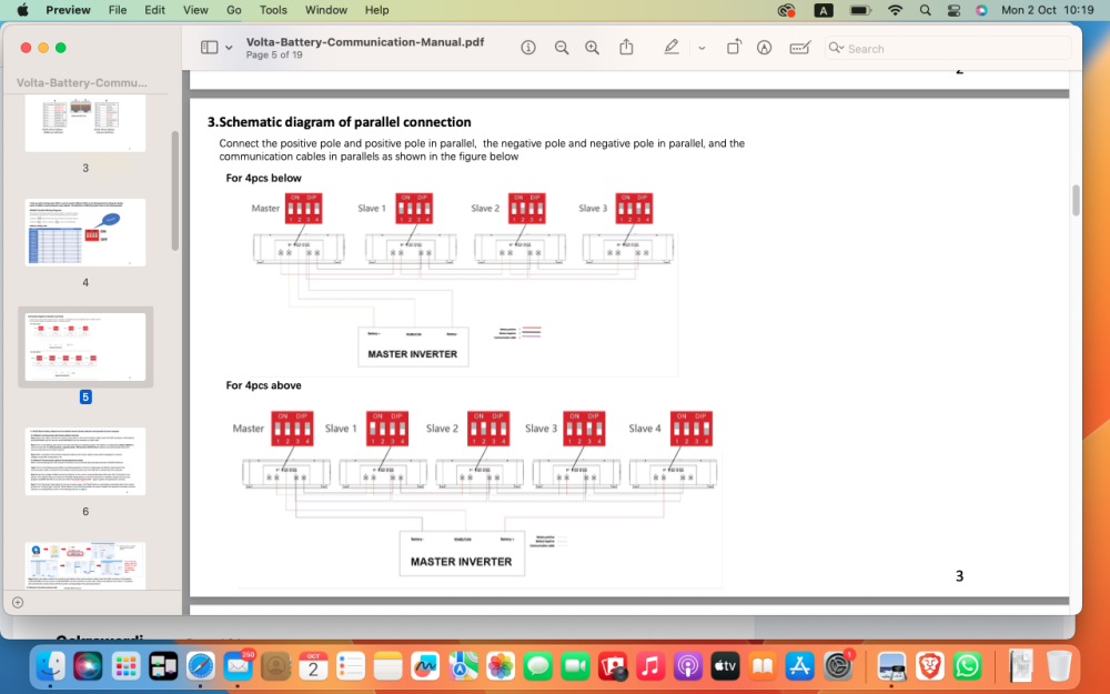
Thanks!So the solution is to update both FW - DSP and MCU? to 25.11 and 12.18 ?Instruction from the seller to use it: Find the local ip address for your device. Create the link that will look: http://your local ip address here/hide.html Connect to the same wifi with your inverter. open link in the browser. You'll get upload page. select file and upload. reboot the inverter. W71(2M)K11-v1.44.5_SolarV11_upgrade_Cc.binOK. Found all instructions in the files here. latest version it's 25.11 or 25.74 ? I found both here on forum. By the way, the name of the update file, that seller sent me to use for the wifi fix - W71(2M)K11-v1.44.5_SolarV11_upgrade_CcHello Coulomb! I have Ultra 11Kw Sunmart branded. With 25.07 firmware version. It falls onto the F17 High DC offset and F11 High inv amp faults in SBU mode while charging the batteries, or when reroutes the power from the load to the battery, when the load decreases. It works ok in the SUB mode, however. It has non working wifi feature "from the box" which was fixed by the firmware update from the seller (Sunmart). Works with the "Solar of things" app (monitoring only, no settings available at all) , not visible with the isolar app. Visible with Watchpower from the PC through RS232 comm port. Shows W11 comm lost while charging the batteries in the SUB mode, with grey small screen and switched off stripes on the top round screen. Do I have glitchy firmware, what do you think? Seller rep went silent after all this report. Contacted another seller rep today, sent all data again. HW 01.00 DSP: 25.07 MCU1: 08.08 MCU2: 60.03 LCD: 01.00Probably the final update on my situation. Today I've got the Raspberry and installed the Solar Assistant. Connected USB socket of the inverter directly to the USB on the Raspberry, and the batteries connected via RS232. No issues at all. Up and running. Solar assistant see all data from the paralleled batteries, 2 separate packs, with voltage, SOC and temperature. Temperature, however is wrong - 10 degrees lower than it is. Also Assistant see all data from the inverter. Just plug and play. In a while I'm expecting to get RS485 converter for the JK BMS on my third battery so all data will be in one place. Not perfect as if inverter would see the batteries directly, but better than it is was only voltage based. Also, another, probably important thing. The Solar Assistant wasn't able to connect to WIFI made on the mesh system devices. Only to the regular Wifi router. I had similar situation with the home security system before/ so just connected it to the other network made with plain router. It's because of some security protocols incompatibility, in mesh for such devices like Raspberry, etc. Even if you plug the Raspberry to the ethernet port of the mesh system device. Strange but that's what I've noticed.Yes, Junlee manual says nothing about the baud rate. But the Volta's manual (their BMS uses same software for RS232) has something on that. I attached the page from the manual. So it's even more confusing now. I wrote the email to Solar Assistant yesterday with all this story, hope they have the solution.
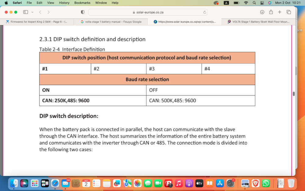 Checked the dip switches in different positions for different addresses. And there appeared the complete mess. So master is definitely 0000. Otherwise no pass through monitoring is possible in RS232. But the dip switches settings doesn't appear in the BMS settings. Unless changed in the TOPBMS software, they are not changing there. If switches 3 and 4 are OFF, RS485 bms address shows as 1, no matter what. If they are ON - RS485 BMS address shows as 2. If any of the switches 1 or 2 are ON - Pmodbmstool doesn't see anything and shows "abnormal". It see the BMS only if 1 and 2 OFF. But 3 and 4 can be ON and it still see battery in RS485-1 port. Still, if Master dip set 0000 and slave 1000 - Pmodbmstool see 1 battery and its cells but capacity is combined from 2 batteries. So it makes sense for Inverter communication. On the other addresses no combined capacity and only one battery shown, which cable is connected to. Another strange thing - Multisibcontrol doesn't see inverter today. WatchPower works as usual. And battery is alarming if RS485 protocol changed to Growatt, SRNE, Infinisolar, etc and Pmodbustool connected via RS485-1 on that time. So these are not compatible I guess.Doesn't work that way either. Most likely the protocol isn't implemented in the proper way. Because the BMS sets bulk and float at 52.5V (Batteries are 15S) and in the same time the manual says - 54.7V, and in the BMS settings I see that Battery Full V setting is 54V. So inverter doesn't read the data from the BMS correctly. Will try another dip switch settings. I saw in the Volta batteries ( I actually found the topbms software recommendation on their page and it worked ) that the 2 first dip switches changes the CAN from 500K to 250K speed. And it's definitely has impact. Addressing Master also sits on same pins. So it's another adventure. I've got response from the TOPBMS - www.cleverbms.com today. They said that they pretty sure that my bms is not their, just similar, and they refuse to provide any advises, because they afraid that my bms might be damaged because of some manipulations they might recommend. But they insisted that if BMS responded to their RS232 software and doesn't communicate properly to Voltronic - so they sure it is not able to communicate to Voltronic in particular. May be they can communicate to the other inverters but not to Voltronic. I'm more and more looking to the side of Solar Assistant now. Because I definitely see that I can pull data from the battery via RS232 or RS485 and can connect to the inverter via RS232. If I will not find the solution in direct communication will go to the Solar Assistant.This didn't worked either. But, good news - I switched the RS485 to Pylontech and tried to connect monitoring software via RS485-1. And Pmodbmstool worked. It shows 2 packs as single battery with 200AH, but shows cells on only for the master battery. Still it doesn't show the second battery as separate pack. And when I made same for the second battery (switch protocol to Pylontech) the software didn't connected and showed "abnormal" connection status. I suspect that may be the reason in the dip switches. I made as were recommended in manual for master and slave ( for the Master - all switches OFF, and for Slave 1 - ON OF OF OF). And made RS485 ADDRESS for Master in software settings as 0. But I read that some for some BMS it is also important for pass through communication to have correct dip switch settings on each battery, as it has influence on the boud rate. So If inverter see the first battery but doesn't see the second, it may cause issue, I guess. Because when connected under the Darfon it see batteries as Group1 Pack1. Not sure but supposed to be Group1 Pack2, as there are 2 batteries. Another good news - I connected to the inverter with Multisibconrol monitoring software and it showed Inverter as 054/MKS2-5600. So now I suspect that my Axioma's hardware inside is Axpert MKS2 with new touchscreen from MKS4. But all it's connectors are exactly as MKS4 - COM, BMS, mini USB... I wanted to use Multisibcontrol to monitor batteries via Pylontech protocol, but didn't succeed.Yes, I wrote to them earlier but no answer so far. Interesting that there is separate protocols RS485 in the BMS list that should work with Voltronic inverters - Darfon and VoltronicPower. And last one doesn't work at all, with error 61.