


Adil
Members
-
Joined
-
Last visited
Everything posted by Adil
-
Is the inverter putting out any faults? Anything showing on the Alerts page? Have you connected your three phase grid wires to the inverter properly like L1, L2 and L3? These have to be in the correct order to avoid any phase related issues. Make sure they are connected as they are coming from WAPDA. Make sure that Zero-export Power in System Work Mode is set to at least 20W, preferably 40W. Attach your settings for System Work Mode and Battery.
-
I have a Teensy 3.1 lying in the parts bin somewhere. Are you using SN65HVD230 transceiver with it? Do you have details for the wiring, code, library etc?
-
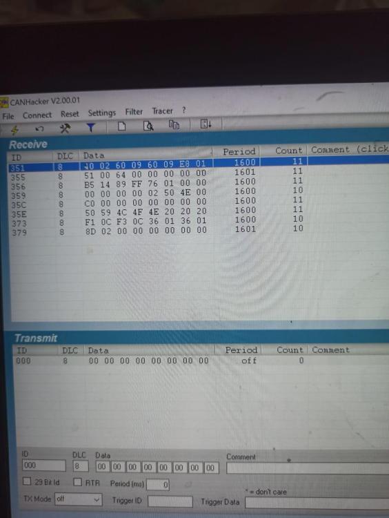
I sniffed the CAN traffic of bms to inverter. I have attached the traffic picture and the document to interpret the values below. In ID 351, the first two bits 40 and 02 are battery charge voltage. As they are following little endian, it will be interpreted as 0240 in hex, which comes to 576 in decimal i-e 57.6v, which is what we are seeing on the inverter. So it is now confirmed that the 57.6v value is being sent by the bms to the inverter. I don't understand why the bms will do it. PbmsTools software which everyone uses to modify Pace bms doesn't seem to have any hidden settings. So I guess I have to find a new firmware for bms to handle this or someway to change the value going to the inverter. Thanks everyone. PYLON BMS Protocol _CAN_ _Can_20161103.pdf
-
Cells cannot be replaced. They are ultrasonically welded. And the battery is no more than a month old with Hithium 314Ah cells. I hope it sorts out itself. As for battery temperature, nothing can be done about it when ambient temperature hovers around 45°C.
-
It does continue balancing the cells but it only has a puny passive balancer which cannot do much. I have received Neey 4A active balancers which I am going to install very soon. The maximum voltage difference at 100% SOC I have seen is around 200mv. It goes down with time when bms is balancing. Average is around 120mv. Hmm. I am changing the parameters in the bms making Cell OV alarm to 3.6v and Pack OV alarm to 56.8v. I will monitor the battery for the next two days by using the memory function in the bms. I will report the conclusions here.

-
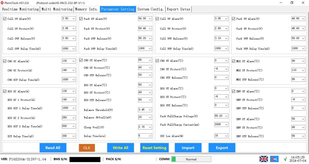
You are looking at the screenshot in the second post where CHG OC Alarm is 140A. My actual bms screenshot is in the first post where it is set to 130A. I understand your point that the charge limit of the inverter is 240A so it might not show any higher value even if it is set in the bms but I am still stuck with the voltage issue which is the primary problem. Every time my battery reaches 100%SOC it is usually because some over voltage protection is hit. The bms cuts off the charge amperes and as the voltage is higher than Pack FullCharge voltage of 55.2v it changes the SOC to 100%. My battery goes from 90% to 100% in five minutes.

-
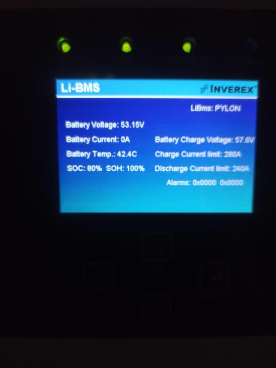
No, it is not. As I mentioned above, all three values do not correspond to the display on the Deye inverter. The main problem I have is the Battery charge voltage of 57.6v which I have set to be 55.2v. I want the inverter to charge my batteries at 55.2v and when the voltage is reached, soak up the remaining power by reducing amperage. Charging with 57.6v has the potential to run into Cell over voltage protection of 3.65v.
-
This is the screenshot I found in Gobel Power battery manual which also uses Pace bms. It shows which values are sent to the inverter It says in the manual: Some important values are sent to inverter, such as: A. CHG OC Alarm (A) : Max Charge Current Limit (CCL in Victron) B. DSC OC Alarm (A): Max Discharge Current Limit (DCL in Victron) C. Pack FullCharge Voltage (V): Max Charge Voltage Limit (CVL in Victron)

-
I am having some issues with my 16kWh battery with Pace bms to show the right parameters on Deye 12KW 3 phase inverter. Battery Charge Voltage, Charge Current limit and Discharge Current limit showing on the inverter battery page do not correspond to the values set in the Pace bms software. Battery is communicating with inverter on CAN with Pylon protocol. There are two batteries connected in parallel. One is master and the other is slave with corresponding addresses of 1 and 2. I have tried Pylon RS485 protocol and it did not solve the problem. My understanding of the parameters is as under: Pack FullCharge Voltage should be equal to Battery Charge Voltage. Currently >>>(55.2v/57.6v) CHG OC Alarm should be equal to Charge Current limit. Currently >>>(130A/140A) DSG OC Alarm should be equal to Discharge Current limit. Currently >>>(130A/120A) Value of 280A for Charge Current limit and 240A for Discharge current limit is for two batteries. If I disconnect the second battery then these values will change to 140A and 120A respectively. Any help will be really appreciated.
-
As discussed above, it is not a problem. The best solution is to attach batteries. Otherwise, it still works as a grid tie inverter during the day.
-
I really appreciate your help. It made things clearer to me. At least I can say that there is no problem with the inverter. Thanks
-
So that means that the inverter itself is powered only by PV? Grid has no ability to power the inverter in absence of PV? I understand that the inverter will not work, i-e not supply power to the load, when there is no PV but it should at least not go into a start stop loop while the grid is present.
-
I think I have some deficiency in my understanding of how grid tie inverters work. When the PV goes out in the evening, grid tie inverters shutdown? I thought they will still work with the grid power and only power off during load shedding.
-
Link to a video I made of the inverter in that state of restart loop. https://jmp.sh/s/cP0vWD0luLdixcGlCOUL
-
But in absence of battery, grid power should compensate. I am sending you the latest picture of the front panel right now. It shows power being used from the grid. But after a while, it will go into that loop.

-
I have a three phase 12KW Inverex Nitrox(same as Deye) hybrid inverter which goes into a strange restart loop in the evening. The led lights on the inverter come on and off very few seconds. The screen does not turn on. It remains like that till the morning when sun comes out. This behaviour usually starts happening half an hour or so after PV stops producing any power. I have no batteries installed. It is currently working as a grid tie inverter. I have attached some screenshots of my settings and inverter specifications. Any clue will be really helpful. Thanks
.thumb.jpeg.fe7ea434e471f0ce2b6928354c1d480a.jpeg)
.thumb.jpeg.f55b593f0a6dc633c32a783de34f7944.jpeg)

.thumb.jpeg.7ce26b3447d977bd785154dc422ab281.jpeg)


.jpeg.5fd43d2ca0a841a9483562f451d03c20.jpeg)
.jpeg.7b790326f6beb5fd59ef5e54f0c0e47e.jpeg)

.jpeg.2c02d70fc08eca815f94b2aca4c68b1d.jpeg)

