


c3poh
Members
-
Joined
-
Last visited
-
Hi everyone, (Cross posting this from 4x4community.co.za - I suspect this is where the experts hang out) I’m looking for advice on sourcing a specific type of valve for my solar thermal system, or recommendations on local suppliers. System Setup: Sonnenkraft indirect solar thermal heating system using propylene glycol fluid. Dual-circuit setup running off a single collector array. Circuit 1: Primary loop heating the hot water cylinder (driven by a Wilo Star-RS pump). Circuit 2: Secondary loop dumping excess heat via a heat exchanger / pool circuit (driven by a Wilo Star-ST pump). Both pumps are mounted side-by-side on parallel pipe legs branching off a common manifold. The Problem: Neither Wilo pump has an internal check valve built-in. When Pump 1 runs to heat the tank, the pressurized glycol takes the path of least resistance and back-feeds in reverse through the idle Pump 2 on the pool loop. The same thing happens in reverse when Pump 2 runs. This parasitic short-circuit loop robs the system of thermal efficiency. (The system was working perfectly, but after a renovation and re-installation (paid for), it has been a disaster) Current Temporary Fix: I have manually isolated the pool loop by closing its ball valves, forcing 100% of the flow through the cylinder loop. This works for now, but I need an automated, permanent solution so both circuits can run as intended. What I Need & Technical Specs: I (think I) need to install two inline spring-loaded non-return valves (check valves / gravity brakes), one on each pump leg. Because I’m not a plumber, I want to make sure I get the exact right component. (I'm somewhat handy and have managed to replace one part already and re-fill/pressurize the glycol fluid - so I'm hoping this isn't rocket science) My understanding is that the valve needs to meet three strict requirements: Low Cracking Pressure: It must open under very low pressure differentials (around 10–20 mbar / 0.15–0.3 psi) so the Wilo circulation pumps don't struggle or lose flow rate trying to push them open. High Temperature & Glycol Resistance: Must handle high-temperature solar glycol (rated up to at least 130°C–180°C continuous, with Viton/FKM or PTFE seals). Standard hardware store brass check valves with rubber seats won't last. Sizing: Designed for 22mm copper pipe (typically a valve with 3/4" female BSP threads or 22mm compression ends). Does anyone know of a local plumbing/industrial fluid stockist in Cape Town (or a specialized SA online supplier) that carries solar-rated spring check valves fitting these specs? Any leads or alternative plumbing strategies would be greatly appreciated! Happy to source from abroad too if needed. Also happy to pay someone competent enough to come out and install the valves (provided they are the correct spec) Much appreciated
-
Will follow up with installer as to how the load is split. At this stage I know that the entire house is powered (incl heat pump) even when the utility is down (load shedding). One other question. In advanced settings is “Equipment mode : slave” correct. Seems odd since there is only 1 inverter.

-
Oh, and my inverter is right next to my db board. Unless there is a lot of loose wiring I’m assuming that the CT coil is of normal length (where can I read up about what this is)? Quite possible that it’s backwards. Will ask the installer to confirm on Monday
-
Greenfields - thanks so much for the advice. I’ve made the following changes: 1. Turned off the timer 2. Set the trickle to 0 3. Set the mode to “zero export limit to load” I’ll post an update when during the day one we get some sun on the panels. Regarding the trickle feed (just getting my head around this). If I understand correctly when set (to say 20) this should ensure a minimum feed FROM the grid of 20w at all times. Interesting that in I’ve been seeing a feed of 20w TO the grid at all times. For the record, these were my timer settings. It’s off now.
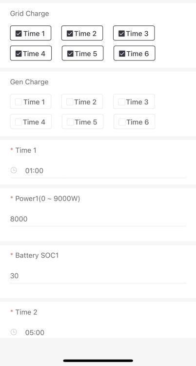
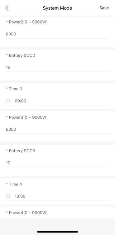

-
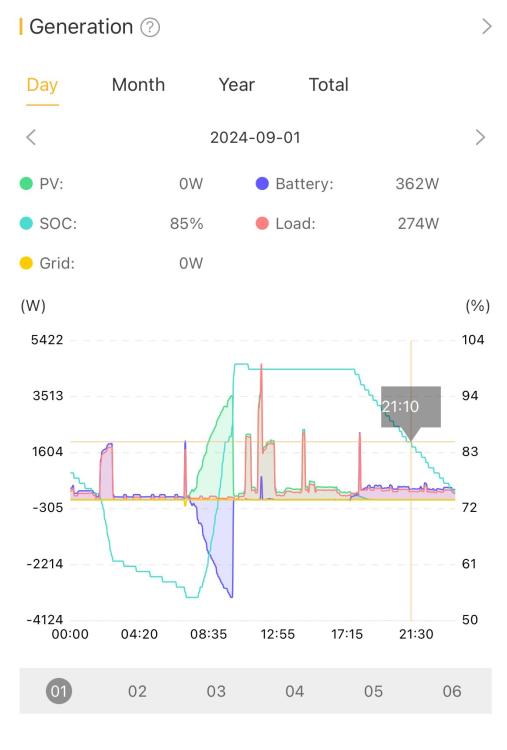
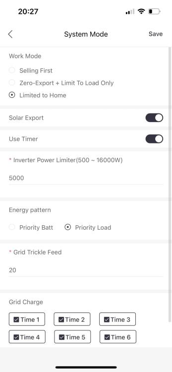
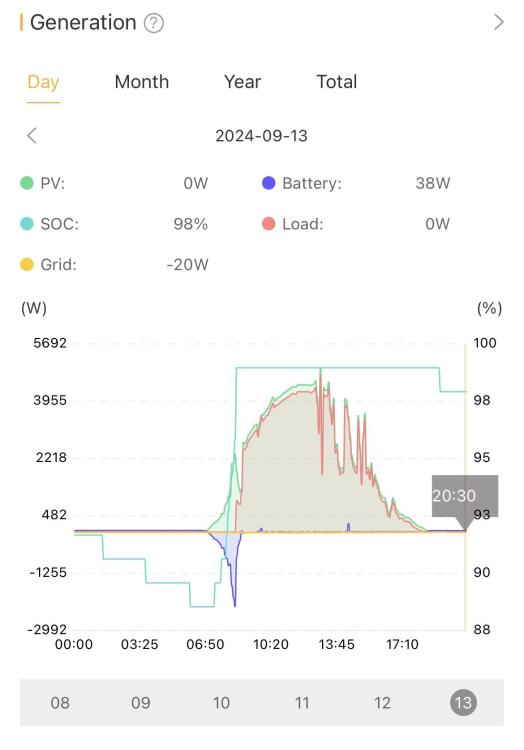
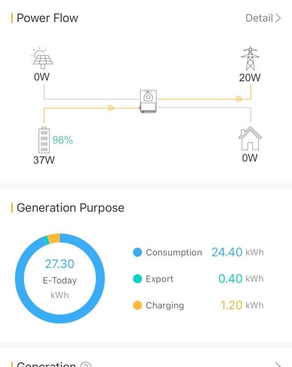
Hi I've had a Sunsynk 8kW inverter with 2 x 5kWh batteries with 14 x 405 W panels for about 6 months now. Small house, heat pump, entire load covered by inverter. It's been working just as expected, load is prioritised during the day, batteries charge and then discharge at night etc. On sunny days, there is negligible draw from utility (Eskom). At this point no feedback into the grid (normal prepaid meter). A typical day looks like the first image posted and is entirely expected, viz, battery starts off low, sun comes up and PV picks up, covering load and charging battery, batteries get full and then PV drops off to cover load. Sun goes down and batteries cover the base load (+- 270W with spikes when heat pump runs). See first image (before.jpeg) This week I got an AMI meter installed (City of Cape Town). Apart from removing the prepaid meter, COCT didn't touch the PV setup. The PV installer then logged on and configured the system remotely to push back to the grid using the following system settings (see second image: AMI-settings.png) Work mode: Limited to Home Solar export: [enabled] Use timer [enabled] - this setting didn't change Inverter Power Limiter: 5000 Energy pattern: Priority Load Grid Trickle Feed: 20 Since the AMI meter installation and changes to the settings, I've noticed some strange behaviour. The third image (today.jpeg) and fourth (flow-consumption.jpeg is the profile for today which illustrates this behaviour. The flow screenshot was taken today at 20:46 - well after sunset. Here's what I'm seeing The battery doesn't cover the load at night and remains almost fully charged Throughout the day and night there is a consistent 20W being fed to the grid At night the no load on the house is present any longer (0W). I would expect to see at least the base load (370W) During the day, the batteries charge first back to 100% - this doesn't take long as they have hardly discharged, and then the load line almost mirrors the PV line throughput the day. I can guarantee you that this is not the real load that the house is drawing. Its almost as if the load line has replaced the grid line, but on the other side of the graph (from digging into examples, I'm expecting the grid line to display negative as the power is fed back). Does anyone have any idea what is going on here?
-
Thanks folks. Much appreciated
-
c3poh joined the community
-
Hi Just taken this battery out of a radio controlled car. Appearance of 2 AA sized batteries encased in plastic sleeve. The label reads 14500/500 mAh 3.7 V How do I interpret that mAh value? Will try to upload an image if I can figure out how.


