


TomasCrespo
-
Posts
62 -
Joined
-
Last visited
Content Type
Profiles
Forums
Gallery
Blogs
Events
Store
Downloads
Posts posted by TomasCrespo
-
-
1 hour ago, Coulomb said:
It's a warning, not an error.
You may not have connected your last battery module when it was at a similar state of charge to the others. It will have trouble balancing the modules. It may be worth disconnecting the newest module, and waiting for the other modules reach a similar state of charge before reconnecting it.
I believe that warning 69 arises specifically as a result of a "Charge Current Limit is zero" message from the BMS. It likely means that one cell is in danger of getting overcharged.
Following Coloumb guess, you should disconnect your new battery, connect only your 2xUS2000 and charge them at 100%. Then disconnect your 2xUS2000 batteries and connect your 1xUS3000 battery and charge to 100%. Then connect all the batteries.
-
The only idea I have to avoid my batteries go off, is put a smart-switch (something like sonoff switches) in the cable between Pylon and inverter. That way I could "disconnect" the batteries to avoid they auto power off, and at sunrise "connect" again the batteries.
On 2020/02/07 at 2:21 PM, Wilfred said:won't it be better (I know it is expensive) to add another brick?
I will do it in a near future.
On 2020/02/07 at 2:21 PM, Wilfred said:Is there maybe a load that you can reduce for that early morning/night time hours to reduce battery depletion
Yes. I use ICC + Home Assistant to control the instalation, so if the batteries are discharging too much I switch off almost everything.
-
Your are right.
The thing is that I would preffer that inverter were off before batteries were off. I think if low cut-off voltage is reached inverter will not use the batteries and hence will switch itself off (because I don't have any source of energy). At sunrise, inverter will go on and recharge the batteries.
Currently the low cut-off voltange (47v) is never reached. When batteries get below 10% they auto shut off, and their voltage is above 47v.
This morning example, at 19% it is 48v.

It will be great low cut-off parameter could be set at 48.5v or even better, set the low cut-off paramter by SoC
-
Congratulations, communication between your inverter and your Pylontech is definitively working
19 hours ago, Watt_The_F said:now assume that the battery is adequately protected without any additional controllers required (I hope). The low DC cut-off voltage (program 29) is set at 47V. The bulk and floating charge levels (program 26 and 27) are set at 53.2V.
However, one note about this. Firstly, I'm not totally sure about this, I had only one experience for the moment. The low cut-off voltage parameter has no sense with Li-ion batteries. It has sense for acid batteries. Your Pylontech battery will auto-switch off itself as protection measure, before 47v (max cut-off value in Inverter).
I have that configuration, I have no grid and I have set low cut-off voltage set at 47v, but this winter with various cloudy days my system went off one night. However at sunrise my system switched on (because VMIII can work without batteries), but at sunset my system was off again. Next day same history, with the sun all working (pool pump, security cameras, internet connection...), with the night all off. I connect remotely to that installition during working days and only visit the installation on weekends.
When I got there I realized that Pylontech batteries were off. I had to switch it on manually. Inverter can NOT even charge the batteries when they are off
My guess are:
- If Pylon discharge deeply they auto switch-off, before inverter's low cut-off voltage been reached. Inverter can NOT charge the batteries even with a lot of sun until you switch on the batteries manually
- I suposse that if Inverter's low cut-off voltage were reached, the batteries will not auto-switch off, so, at sunrise they will be charged correctly.
-
14 hours ago, Watt_The_F said:
Option A (TomasCrespo)
Inverter <--> Pylontech
Pin 1 <--> Pin 3
Pin 2 <--> Pin 5
Pin 3 <--> Pin 1
Pin 5 <--> Pin 2
(no other pins connected)
I purchased an Axpert VM III and I received the original BMS cable, but it was not long enough, so I made the one in the pics with the same pinount.
Its working perfectly for about one year. Of course I have configured the inverter in PYLON mode. If I disconnect the BMS cable the inverter beeps with error code 61 (I'm not really sure about the code number). If I connect again error disapears.
This pic is the original cable I received:
-
-
Wow! Great explication Coulomb, thanks!
Not scared, I've done similar things with some machines, but in any case... too work! And even if I would have the JTAG... I dont have the password.
For the moment, I will try that the seller give me a firmware update (I think he won't do it). As second option, I will flash the firmware you linked (20.59) and then test if my bad readings of pv input are corrected. It will be great if anybody had tested that firmware upgrade file first

Lot of thanks
-
41 minutes ago, Coulomb said:
There is, but you need a password and some slightly unusual hardware. I actually extracted a firmware from a very early machine, before they started using passwords.
I have the hardware here, and I actually have a clue as to what the password might be, but it's a very long shot. Also, I don't have a VM III machine here.
So: not practical, unfortunately.
Anyway, I am interested in the process. I want to know the hardware and the process. Is there any info in web or could you make it public?
I understand it is a difficult process, and I likely won't do it, but I am curious.
By the way, I am an IT profesional and I have worked with electronic circuits other times.
Thanks
-
Thanks for your reply.
No way of backing up the actual firmware?
-
Great info!
How do you know that file is 20.59? It only says version 1.0.0
How safe is updating firmware in this inverters? Could I brick it? Could I revert back to my previous version (backup first or download from anywhere)?
I think I read something about VM III with mppt dip or freeze, and I don't have this problem, so I'm scared about the firmware update could give that problem.
-
On 2019/08/12 at 12:24 PM, Coulomb said:
Yes. But for technical reasons, it's hard to write a general monitoring program to get at those values, that works for paralleled as well as single machines.
Hi! Coulomb, finally the seller has confirmed that they are having this problem (erroneous pv input readings) in their VM III and King models. They told me that are speaking with voltronic to find a solution (firmware update perhaps), but they are not very confidendt about getting the firmware update.
It looks like other people its not having this problem with their King or VM III. I suppose because its another maker (Easus, Inverex...). Mine has no a specifc brand, but the seller is a trusted seller. I don´t think he sells clones.
Could it be possible to update my unit with the firmware of another one?
Currently my firmware is:
U1 20 25
U2 01 21
U3 00 21 -
Inverter LCD screen values (pv input Watts) and ICC pvwatts are identical.
So my problem is the same looking at ICC data or LCD screen data.
My inverter show me less PV Watts than Load Watts
 . Obviously this is impossible, because there is no mains and battery is apporting 0 Watts.
@mazo78 Was this your problem? Was solved reflashing the unit?
-
On 2019/07/30 at 5:20 AM, Dex_ said:
I see.
for interest sake what firmware version are you on?
I'm not sure how to check firmware version, but in ICC Inverter values I have:
Main CPU: VERFW:00020.65
-
On 2019/08/11 at 11:51 AM, Coulomb said:
Yes. I think that ICC probably uses the QPGS command to get most of its data, needed for paralleled units (I know you don't have paralleled units, but the same monitoring software has to work with singles and paralleled units). QPGS doesn't have the total PV power in Watts (a bad omission it seems to me), so the PV power has to be calculated from net charge current times battery voltage plus load power times a fudge factor for inverter efficiency. The net PV charge current is provided only in whole amps, so with a 52 V battery you will only see 0/52/104 charging Watts for 0/1/2 A of net charging current.

And what about Inverter's LCD screen? Should it show the right values?
-
8 hours ago, Coulomb said:
If the graphs are correct, the rest has to be coming from AC-in. Is that possible? Is your inverter (in these conditions) in line mode?
Absolutely not. I have no AC in. Not grid neither generator. Totally offgrid.
Could it be that the inverter wrongly reads pvwatts when the value is small (< 100 Watts) and it reads correctly when the value is bigger?
I will post inverter's lcd screen pics when I get there
-
Yesterday daylight hours:
As you can see, until 13 the battery is charging and the the figures have sense, pvwatts1 = batterybatts + loadwatts. However when the battery is fully charged I can´t understand the figures; pvwatts1 is not enough to feed the loads, and battery is not apporting anything.
Detail from 13:00h:
-
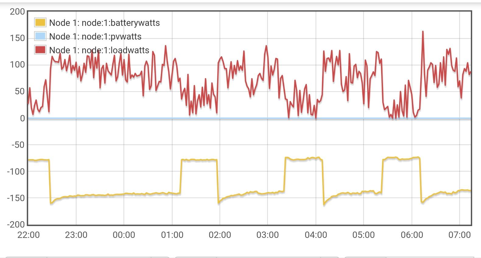
Same graph, but with batterywatts in positive, to easy analyze.
As far as I know, the Inverter autoconsume is not integrated in loadwatts, and it is about 50w. This is the small difference. I mean, the data is ok at night (batterywatts vs loadwatts) but not in the sunny hours (pvwatts1 vs loadwatts)
-
On 2019/08/08 at 2:04 AM, Coulomb said:
I wonder if your monitoring software is using the "MPPT charging current" figure and multiplying it by battery voltage to come up with power. But this isn't total panel power, it's net power into the battery. The PV power figure from the LC Display (available from commands such as QPIGS) is the total panel power. If I recall correctly, the PV power figure comes from the Solar Charge Controller, but the PV net current figure is estimated using various assumptions.
Hi! I'm using ICC as monitoring software. The graph is from emoncms, with the data that icc provides. The figure is pvwatts1, there is also a pvamps1, but I'm not logging that one.
I'm not sure if the value of pvwatts1 in ICC is exactly the same showed in the Axpert LCD screen (PV Watts input) but I will check.
Below a graph in the night, when thee is no solar production. You can see batterywatts instead pvwatts1. I think in this case the data is OK.
-
HI, I have a similar problem. I think my VM III is not reading PV input values correctly.
However it is working OK.
I am offgrid, any mains neither generator. Only 8x330w panels and one Pylontech US2000B module.
My load is almost constant, around 150w, but when sun is up my inverter says that he is catching 0w from the battery and 8w from the pv solar panels. All my loads are working perfectly.
It is not a lag. This behaviour is the same the whole day. Pv Watts are much lower than loads and all works. A imposible thing, so the pv Watts read should be wrong
Remember, there is not any other source of energy. No grid,and battery is aporting 0w
-
They replaced the unit. They said that it wasn't possible with only a firmware update, they said that there were some hardware changes, but I doubt that there are hardware differences, I think is only firmware.
Anyway, I can't observe any advantage of having the Pylontech compatible firmware or not. My main concern was about the "cut voltage" parameter, and it has the same values in both firmwares
-
9 hours ago, RichieRich said:
The only thing i can think of is using the home automation feature of ICC and connecting a relay to turn off the inverter feed out when the battery gets to 50% SOC?
You can also use the Advanced power management with the wireless POW's but the max amperage is 16amps per POW so you may not be able to use one just one the out going supply. but if you use 2-4 POW across different circuits you my have more flexibility as what SOC things turn off. So some items turn off at 65% SOC and others at 45% SOC.
Good idea. I suppose I will do that if there is no easier option
-
I take the opportunity to ask one thing
My scenario is a totally isolated cottage, so I have no grid, neither generator.
I would like to stop the system when batteries are at 50%. I have tried the "Change to grid" option in ICC solar, but when I reach 50% of SoC nothing happens. I think it doesn't change to grid, because there is no grid.
How could I make the system stop (inverter off or standby) when batteries are at 50% (or any other value of SoC)?
I think my only possibility is using cutoff parameter on inverter, but it only reach as much as 48v, and I don't know (yet) what SoC is equivalent to 48v
Some idea?
-
3 hours ago, RichieRich said:
Well hopefully when the next firmware is available the BMS port will be enabled on the king. I’m using ICC to control my king at the moment so it’s not too much of an issue. But it would still be nice for the batteries to communicate with the inverter.
I'm trying to determine if there is any advantages of having the Pylontech enabled firmware (once you have ICC).
Now the inverter know the right SOC, but... for what? This is useless
The real advantage would be that the inverter read the battery voltage through the BMS instead of calculating by itself, because there is some parameters related with the battery voltage:
* Change to grid
* Change to solar
* Battery cutoff
I'm not sure about if the inverter reads the battery voltage through the BMS or not. I'm testing yet.
I have read in some post that some of you are using floating voltages below the recommended by Pylontech. If you select Pylon in Battery type, you couldn't change the floating voltage. Obviously you could select "user define" in battery type, but then you will lose BMS communication...
 Or not? I will test it too
-


VM III not saving max charging current
in Inverters
Posted · Edited by TomasCrespo
Hi!
I have a Voltronic VM III 5k with only one US2000 Pylontech module, so I set the Maximum charging current (parameter 02) to 20A. It has been perfectly working for one year, charging the battery in the mornings as far as 20A (about 950W).
Now I have purchased another Pylontech module, US2000 too. I have connected both and they are working. My Voltronic VM II has Pylontech support and it informs that there is two modules in the LCD display. Also ICC inform of the two modules and its voltages, temp, ...
So I proceed to change Maximum charging current parameter to 50A, but it come back to 20A after a few seconds. I have tried from the LCD display, from Watch Power bluetooth app, and from ICC.
It looks like if it is applied for a few seconds, I can see my batteries charging at 1500w, but suddlenly come back to 950w. I double check the Maximum charging current parameter and it is at 20A again.
It is like if Pylontech battery communicates with Inverter and replace the parameter
Any similar experience? Any clue?
The only idea that I have is changing the modules position, set the older module as master.
Of course, my two US2000 batteries are different versions, because they were purchased with a year of difference. I have put the newest as master battery.
Newer Pylontech US2000 part number: US2000NB02V00101 Date of production: 2020-31-15
Older Pylontech US2000 part number: ?¿ (I will update)
Voltronic VM III firmware version: 20.25