


Riff-Raf
Members
-
Joined
-
Last visited
Everything posted by Riff-Raf
-
Useful information, thank you. I have a slightly different question related to battery settings... If I have 2 inverters (paralleled and communication properly) and 3 x 200Ah batteries (600Ah in total, joined with a busbar) what the Capacity setting in each inverter should be? 600Ah or 300Ah. Battery settings seem to be inverter specific as you can set different charge current in each inverter. Does the capacity setting accumulate as for the charge current setting or is the setting reflecting total capacity, irrespective of which inverter you set. I ask this as when you set charge current, it is set per inverter, so if each inverter is setup to 40A, the total charge will be 80A (I have tested and observed this) Curious to what everyone else is using in their multiple inverter settings.
-
I wish I could say the same... Impossible to communicate via e-mail. My one ICC pi license (ICC sourced, not Centurion Solar) just decided to de-register. After a few attempts to re-enter this, the ICC software then removed the Register button altogether. Same Machine ID, Same Key. I even resorted an old image backup I made from October 2021 (ver 4.8), with same results. When the pi is not connected to the network, it shows REGISTERED until..., if connected, then reverts to UNREGISTERED. Any ideas why this would be happening?
-
I have recently purchased the MECER 3kW 24V inverter (SOL-I-AX-3M-24) for a non-solar work backup / UPS setup and it seems to be behaving strangely. I have installed many 5kW inverters, mostly solar and connected to the Pi ICC monitoring software so I'm familiar with the bigger brother inverters to the 3kW. I am also familiar with the screens and programming an all these units, but this one has stumped me... My question... When this inverter is charging (I measured with a clamp-on amp meter to make sure it was charging), the inverter display for battery amps shows 0A even though it is delivering 20A to the batteries. When discharging it shows the correct -A. I have also connected it to a Pi with ICC and it's the same, shows discharge Amps, but 0A while charging (even checked in the data feed values as well as emoncms feeds). Looks like it just does not report charge amps. Does anyone have any wisdom to share with this? Could it be a firmware issue which may need an upgrade? I hunted for newer firmware, but could not find it anywhere. Current firmware is: V1-02-73 Your insights are appreciated... as always
-
You are braver than me... I would think that the units need to have the same firmware version when using in parallel. As some of the settings carry through to both units when paralleled, irrespective which unit the setting is applied, it would be logical to have both units' firmware the same. There may be some reporting protocol difference between firmware versions, hence your PV data reporting issue. Unfortunately, I'm no Axpert at the data protocol level 😏
-
I'm running 2 units in parallel which have 71.50 firmware and everything works perfectly
-
After my initial upgrade issue and Mustek generously replacing the control board under warranty, I frankly don't have the guts to do any upgrades. Also changed to Lithium batteries, so the inverter works perfectly with the original firmware. Would be good to know if there is a new firmware though.
-
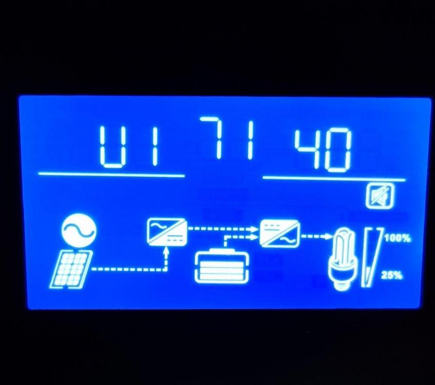
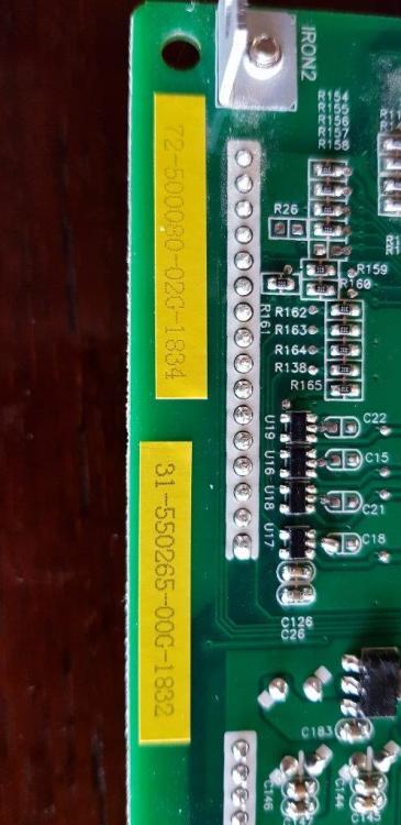
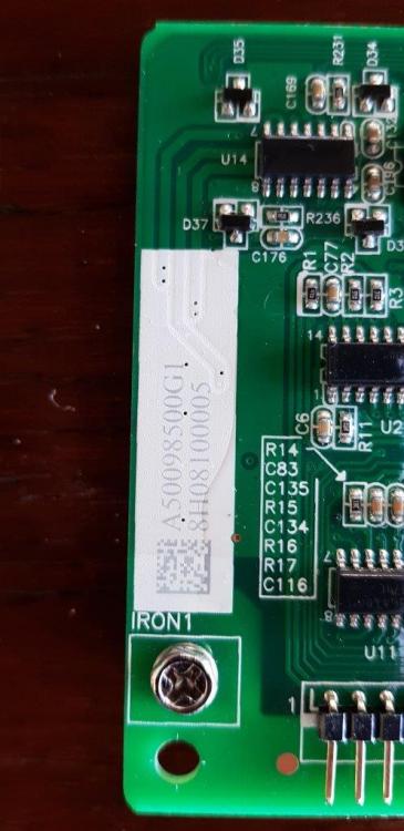
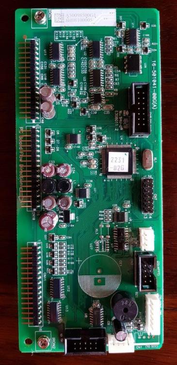
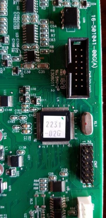
Firstly, thank you for the continued follow-up and interest. I appreciate the support. Yes, I asked a buddy of mine who has the same inverter to send me a pic of his stock version. It is 71.40. If you have any idea where I can source this, then I can try to load this version back to revive my inverter before I try to buy a new control board. I have also attached pics of the control board for reference.

-
Sadly, yes. Luckily i have a second inverter. Just to confirm then... Is the firmware http://forums.aeva.asn.au/viewtopic.php?p=70004#p70004 also NOT SUITABLE for my inverter?
-
I have used 18K resistors to replace the sensors (all 3) but no change. In fact I think these are not even read as the temp display remains at an exact 112 deg C. This would imply that it shows some default / fallback value (112) irrespective of the sensor probably due to the firmware not being suitable to process that data.
-
Thanks. This only adds to the challange as these are higher than mine. So if I increase my resistance, then the unit will think it's even hotter (higher temp normally increases ohms?.. I vaguely recall from a decades old electronics class). Worth a try?
-
I am still persevering... I have the correct firmware now (I think) for the HV, 1.0 PF, 64v unit which I found here http://forums.aeva.asn.au/viewtopic.php?p=70004#p70004, thanks to Jaco. Tried a lot of things: Tried the recovery options in 'Bricked' post http://forums.aeva.asn.au/viewtopic.php?title=pip4048ms-inverter&p=59897&t=4332#p59897, no luck... Disconnected the temp sensors, same noises... Isolated the control board, nothing... Changed port numbers and baud rates... Used the same cable and port setting that got me into this mess in the first place using an old laptop with a RS232 serial port... Tried the above over and over, expecting different results (I think this is the exact definition for 'insanity'). BTW, I am an engineer, but the completely wrong kind (mining) and am trained to blow things up, so this is all way above my current pay grade. Next step is to buy a new control board with the stock firmware. NEVER GIVE UP!
-
The thermocouples are 12.5k each. Measured the 3 I can find, 2 on the big heatsinks (mosfets or power transistors, I think) and one somewhere inbetween. What are the typical resistance values in the standard MKS units? Maybe I can fool the processor by inserting resitors in place of the sensors.
-
Also tried that, no difference. I have also disabled alarm (18). It looks like the error just blocks everything. I have also diconnected the Control bBoard from the main board, but no difference. Not sure where the control board gets it's power from., but looks line it comes from the main switch (48v) to the comms board then to the control board.
-
Thanks for the advice, but have tried that already. I opened it up yesterday and unplugged the 3 sensors (thermocouples), but same result. I think the issue is that the sensors don't register at all with this firmware rather than provide an incorrect value.
-
Thanks for your reply. I agree, it is quite a mess. I have searched the net for suitable stock or compatible firmware, but without success. I was also pretty sure that the upgrade wouldn't work if there was a firmware mismatch, but the process was smooth and flowed exactly like the proocess outlined so I was quite pleased with the outcome... until I switched the imverter on again. I saw the 'bricked' post and will try the timed recovery steps as soon as I find the right firmware. But this is proving to be a challange. I should try doing this in a freezer to compensate for the Temp scaling difference and fool the thermocouple (3 I beleive) that it is overreacting. All this just to try squeeze extra 2v range from my Li (15s) batteries. My battery min low voltage is at 40.5v, the inverter only goes down to 44v min for low volt back to utility cut-off.
-
I am new to this fantastic forum and having recenlty upgraded my years' old solar installation to a more intelligent system, I decided to join to get insights from fellow solar junkies and am seriously impressed by the generous sharing of information here. Apologies if this is covered elsewhere, but I was unable to find a related thread on this forum. I have the Axpert MKS II (5kW) inverter (Mecer brand). This is the one which can take PV voltage up to 450v, thus allowing thinner cables between PV and Inverter. So ... I decided to do a firmware upgrede to the Patched 73.00c found here http://forums.aeva.asn.au/viewtopic.php?p=67551#p67551 in order to better tune the voltage ranges for my Li batteries. The upgrade process wen well and exactly as per the instructions. Took about 8 minutes and then all finished as planned. However, when the inverter starts up, the buzzer goes bezzerk and immediately goes to Error 02 (temperature warning) and switches off within 10 seconds. If I quickly scroll to see the firmware version, the correct (new) firmware appears. Also, a new display shows a temperature of 112 deg C, even though not in use, before swithcing off. Anyone attempted to upgrade the MKS II firmware? Anyone else having a similar issue? My challange is that there is very limited online reference to the MKS II model so I also assumed (probably part of my problem) that the firmware is pretty much standard across the family of 5kW Axpert inverters PIP-5048MS (the MKS II seems to be PIP-5048MG). Is this completely different, are the internals so different that the firmware does not manage the temperature measurement the same way? My challange is that due to the immediate shut-down, It is now pretty much impossible to revert to the stock firmware. Any suggesions will be greatly appreciated.
-
The MKS II can take 450V PV input. I use this as it allows for low current cabling between the panels and Inverter.


