mamont
Members
-
Joined
-
Last visited
Everything posted by mamont
-
Треба спочатку розібратись чому в самій батареї неможете протокол виставити. Чи вже вийшло ? Я якось пропустив ваш пост, тільки сьогодні форум сповіщення прислав на ємейл. Судячи з того що ви написали - зв'зок є, але в самій батареї протокол не підходить і треба міняти
-
I dont know. Check inverter manual about CAN protocols numbers, but ai say me what L51 or L52 is sma can in growatts. Idk...
-
Just change protocol in battery with service software to sma can, roll this topic alot top, look on pins scheme, do patchcord canH->canH, canL->canL, on battery side put in can hole, in inverter try find dyness/deye/pylontech can protocol. Thats all.
-
Привіт. Спробуйте змінити свою стратегію і зробити CAN з'єднання замість rs485. Тобто в батарейках виставте протокол SMA CAN, дріт can-H->can-H, can-L->can-L за схемою, на мастер батареці цей дріт в дірку can замість rs485, у внверторі як видно зі схеми - дірка таж сама, тільки піни інші. І спробуйте перебрати на інверторі CAN протоколи (пошукайте який протокол в інверторі працює з батарейками deye, dyness, pylontech по CAN) SMA CAN в батарейках ritar = pylontech, dyness, deye can(00)
-
Try my united bms framework for create custom modules for your battery : https://github.com/mamontuka/ritar-bms-ha its not hard, read manuals, catch registers, create map, ajust parsers
-
sure if you want try in future CAN connection, you can crimple in cable second pair - can-H->can-H, can-L->can-L, just on ritar side change inverter connection hole from rs485 to CAN, and sure choose another protocols on both sides(in battery and in inverter) so its can be just one universal properly done cable, for both connection types (one pair fror rs485, second pair for CAN, and you will able play with on battery connection hole and protocols on both sides how you want)
-
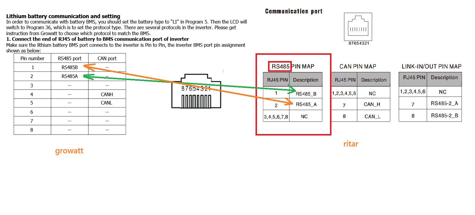
pictures taken from growat and ritar manuals. connect only one pair, another pairs just cut off from one or both sides

-
Взагалі зі сторони батарейки рітар можна земулювати будьяку батарейку і відповідний тип підключення. Як я наприклад показував доку де я під'єднав до деї через кан типа як рідну. Цей фокус мені довелось зробити щоб розділити мережу модбас на два сегменти у інвертора своя модбас мережа, у батареек своя, і між ними кан з'єднання як роутер )) бо при паралельній адресації незалежній інвертора по рс485 та батареек по тому ж рс485 з двох різних гейтів були проблеми
-
В 28у як я розумію треба айді більше ніж має мастер батарейка або остання батарейка зі звязки. Тобто це як айпі адреса, але в мережі модбас - всі елементи мережі повині мати різні унікальні модбас слейв айді. Мастером модбас зазвичай виступає той свисток або гейт для сервісного підключення і він не має слейв айді, але можк адресувати і бачити всю модбас мережу. Дріт правильно обіжми з кінця інвертора, щоб пара а б з батарейки йшла на пару а б на інверторі перехрестно, тобто контакт а на контакт б. Щодо протокола який треба поставити в самому інверторі - то я вже незнаю, нема ніде гровата поблизу, але коли підключення вже гарантовано вірне - то можна підбирати тупо перемикаючи і чекаючи секунд 20, бо воно не відразу підхоплюе.
-
Yes, at this point everything looks correct. Now we need to make sure there's no confusion with the connection holes. On the master battery (DIP ID 1), the IN and OUT are used only for the service software or HomeAssistant integration (IN), and for connecting the next battery, ID 2 (OUT). The RS485 port on the battery should be used for connecting to the inverter (in your case, for the RS485 connection). It works in parallel with the IN for service reading, but is used exclusively for connecting to the inverter. This raises the question of the correct cable crimping on the inverter side. Therefore, you need to check the pinout of the PC485 hole on the battery and the connection hole on the inverter itself. Please note that the picture in the ritar instructions shows the RS485 and CAN holes on the battery incorrectly; in reality, they are marked correctly on the battery. Naturally, the pinout connection should be correct: rs485a->rs485b crosswise, between the contacts in the PC485 on the battery and the hole in the inverter. in inverter also must be setted modbus slave id NOT EQUAL to battery slave id (id 1 setted on master battery by dip switch), because they both will have same id 1 and not work properly. ai tell me what : The default Growatt 5000ES Modbus slave ID is likely set to a specific value, but it is configurable. Users on forums report that the slave ID is set using an "Address setting" on the inverter's display, often found under configuration menu #28. A cold reboot may be necessary after changing the setting. How to set the Modbus slave ID Navigate the menu: Use the physical button to enter Program mode 2 (PM0dE2) and then navigate to the Modbus ID setting page (MOd Id). Enter programming mode: Press and hold the button for a specific duration (5 seconds) to enter the programming mode for this setting. Set the ID: Use the button to select a three-digit value between 001 and 247, as this is the valid range for an individual slave address. Confirm the setting: After setting the ID, save the new value. A cold reboot of the inverter is often required for the new Modbus ID to be recognized. Note: The setting is sometimes labeled "Address setting" and may be found under menu #28. i hope you understand about i say - modbus ids on inverter and battery must be different, on battery id 1 (master battery) on inverter another id NOT 1 about guessing li bms protocol in inverter - its already last thing, before all must be properly connected and setted.
-
Also if you use rs485, on master battery what looks on inverter, must be setted by dip switch properly id 1. On inverter side modbus id must be more than last battery setted ( for example id 5, if you have 4 batteries with ids 1-4)
-
And only after choosing needed protocol IN BATTERY - you need choose properly answer protocol on inverter side
-
And in battery you change rs485 protocol ? Maybe we have alot miss understanding, but IN BATTERY you NEED choose properly protocol too. Thats not stupid one protocol batteries like dyness or deye do. IN BATTERY you can choose from : 0 RITAR_RS485 (RITARV1_8) 1 DEYE_RS485 (Deye BMS Protocol 12), PLY(DEYE,SMK,FIRMAN,Hollandia) 2 GROWATT_RS485 3 VOLTRONIC_RS485, LIB05(VOLTRONIC,XUNZEL,TESLA,GSB SOLAR,PCE) 4 UPOWER_RS485 5 VERTIV_RS485 6 ELTEK_RS485 7 RITAR_MODBUSV1_9_RS485 8 VICTRON_CAN 9 RITAR_CAN 10 SMA_CAN (Deye Protocol 00) 11 MEGAREVO_CAN 12 TBB_CAN 13 SOLIS_CAN 14 INHENERGY_RS485 15 MUST_CAN 16 PYON_CAN 17 LUXPOWERTEK_RS485 18 PHOCOS_RS485
-
Confirm please if will have success in growatt protocol guess, i will add this way to documentation into my repository documentation
-
Im not specialist in growatts, just not have they close in direct access for ecperiments, but we can try guess conection type and protocol... AI tell me : Based on system logic and user experience: In Deye inverters, "Lithium Mode 00" generally signifies communication via the CAN-bus interface. In Growatt inverters, the protocols for CAN-bus communication are located within the L51-L99 range (in the menu setting 36). The most likely and frequently used protocol that works with many universal/generic batteries is L52 (this protocol emulates the Pylontech CAN-bus communication). Recommended Setup Steps: Set the Battery Type to "LI": In the Growatt menu (Program 5), select LI (Lithium Ion). Select Protocol L52: In the automatically opened Program 36 menu, select L52. This is the most common "universal" CAN protocol. Check the Cable: Ensure you are using a standard, straight-through RJ45 Ethernet cable. A straight-through cable is often used for both Growatt and Deye CAN communication. Monitor the Connection: After selecting the protocol, give the system a few minutes. If communication is established, the inverter display should show the correct State of Charge (SOC), and there should be no BMS error codes. And... Im pretty sure what : https://github.com/mamontuka/ritar-bms-ha/tree/main/software_and_documentation/RS485_adapters_and_ethernet_gates/UNDOCUMENTED_WIRING_WITH_DEYE So, by my logic, you need try find in growatt bms protocol what equal to deye 00 proto (can connection, sma type in ritar battery), and properly pinout for cable to connect with growatt. Or by same logic try find equal proto for rs485 to inverter connection.
-
couple posts ago i give all needed links, and tell logic how it works at all. last version 2.80 not have buttons on window bottom, i dont know what you run at all, on your screenshot i see at all not equal soft. i say what bms have OUTPUT TO INVERTER CAN/and/or/rs485 ports, and internal IN and OUT rs485 ports, for uniting ESS (Energy Storage System, 1-15 batteries), rs485=modbus. modbus - have bus id (unit id, battery id, add number - its all SAME meaning). you at first need connect your computer to battery INTERNAL rs485 IN port by last version 2.80 vendor software from links what i give, read this battery in proper way at all. then you need reread post where i say about guessing DIP switches, and find in what kind way modbus id coding works on your board. p.s. buttons in vendor software window bottom, was in VERY OLD 2021 year version... you realy sure what this prehistoric version support newer batteries ?
-
Connection betwen batteries in ess - NOT OVER CAN ! ritar use rs485 modbus where you need set by dip switches modbus id for each battery. Rs485 and can what going on inverter is splitted from internal ess modbus betwen batteries. Only inverter rs485 output can be joined in some cases to internal ess bus. My english so bad, what you not understand me at all ? You now have read atleast one battery from vendor software over rs485 ? Can you show screenshots ?
-
Im already answer about modbus id coding logic (you name it "add"). Several times i say about dip selector. Read my posts.
-
in current reality you able create custon modbus register map (or other modules if need) for United BMS framework, and use addon with any batteries what support rs485 connection : https://github.com/mamontuka/ritar-bms-ha https://github.com/mamontuka/ritar-bms-ha/tree/main/united_bms https://github.com/mamontuka/ritar-bms-ha/tree/main/united_bms/united_bms_ssh_cli
-
also if pin 1 and 2 up 3,4 down - it will be modbus id 3, we need just understand what kind pull up/down used - pin to groud or pin to power
-
so if you have alltime default id 1, maybe DIP selector pin 1 (or inversed pin 4) pulled down to ground (or to + power idk) from factory by soldered onboard circuit ? for example if you have DIP switch - zero number id is all swiches down, last id 15 is all swiches up, id 1 is switch 1 - up (pull to ground or +) 2,3,4 down, number 2 - switch 2 up, 1,3,4 down. Ithink all their batteries have same logic, like in this manual https://github.com/mamontuka/ritar-bms-ha/blob/main/software_and_documentation/Ritar_official_software_and_documentation/documentation/user-guide-rack-type-48v-51.2v-ress-battery-v1.1.pdf and this https://github.com/mamontuka/ritar-bms-ha/blob/main/software_and_documentation/Ritar_official_software_and_documentation/documentation/Ritar_BAT-5KWH-51.2V_User-guide_EN.pdf thats different batteries but selector logic same, in case when no DIP switch at all, i think pin shorted by default to ground or power in this connector, for select id number 1 (master). check this theory by ringing by multimeter pin 1 (or inversed pin 4) to ground in connector or power pin in this connector (sure on turned off board) if im right in my guess, you will able set id how you need, just in easy way and connect batteries to each other with right modbus ids, and take from id 1 master connection to inverter. and sure all batteries will be joined ESS what will readable from master over original soft or from my addon
-
H L and A B - realy look alike connector to inverter with can H and L and rs485 AB. If you did mistake with rs485 AB - will be nothing. But can must be connected H-H and L-L or can be hardware troubles and maybe broke
-
Connector 3 in photo can be temperature sensors, but i Usualy Rs485 its one bus, where devices splited by modbus id. But it can be splitted too. On batteries where connected sockets - you will have rs485 IN and OUT ports for master and slave batteries, and rs485 (maybe splitted bus) for connection to inverter near can bus for same but alternative. Battery can be readed by native vendor software or my ritar bms addon - over IN rs485 port(what paraleled with OUT rj45 cocket, without connection to inverter at all. On factory rj45 rear sockets IN and OUT difference just in crossed tx and rx
-
how i think connector 3 on your photo - is temperature sensors, but im not sure, pinout look alike 4 cells thermometers + environment sensor. mos temp sensor usualy soldered on board. but its only guess.
-
3 connector on your proto i cant guess because marking may be from another board side ))