



Loch
Members
-
Joined
-
Last visited
-
-
 Yellow Measure reacted to a post in a topic:
Repair in Progress: Luxpower LXP Series Parts Availability?
Yellow Measure reacted to a post in a topic:
Repair in Progress: Luxpower LXP Series Parts Availability?
-
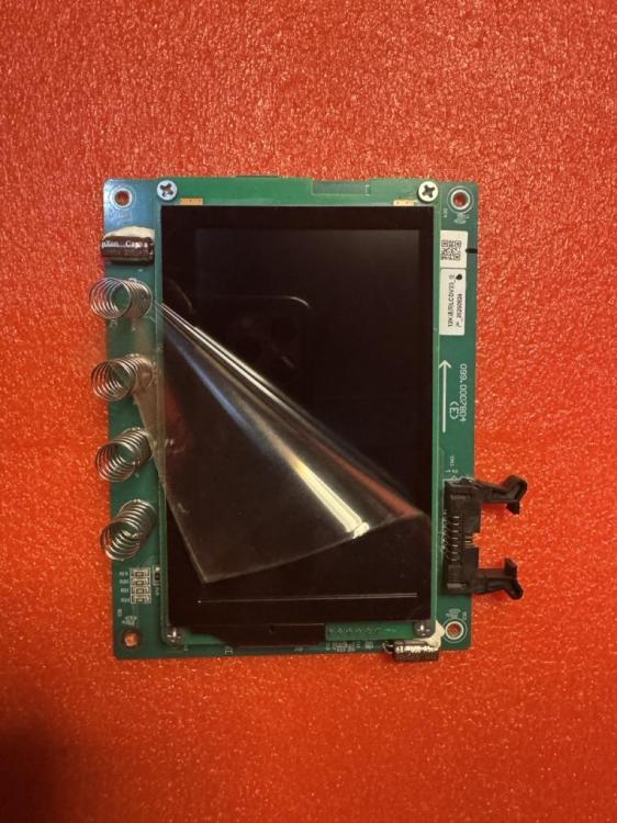
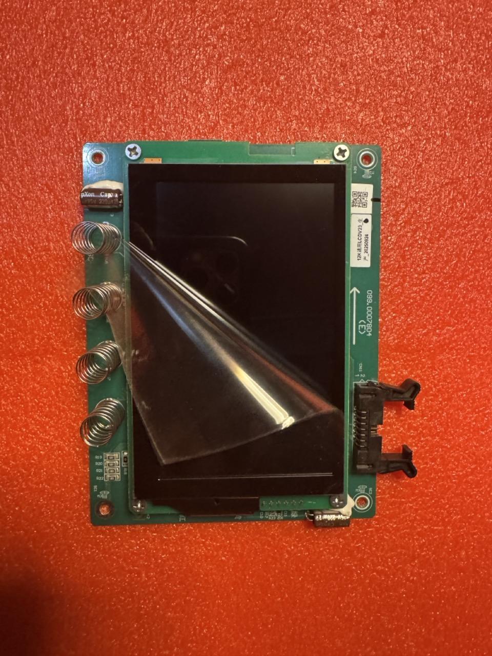
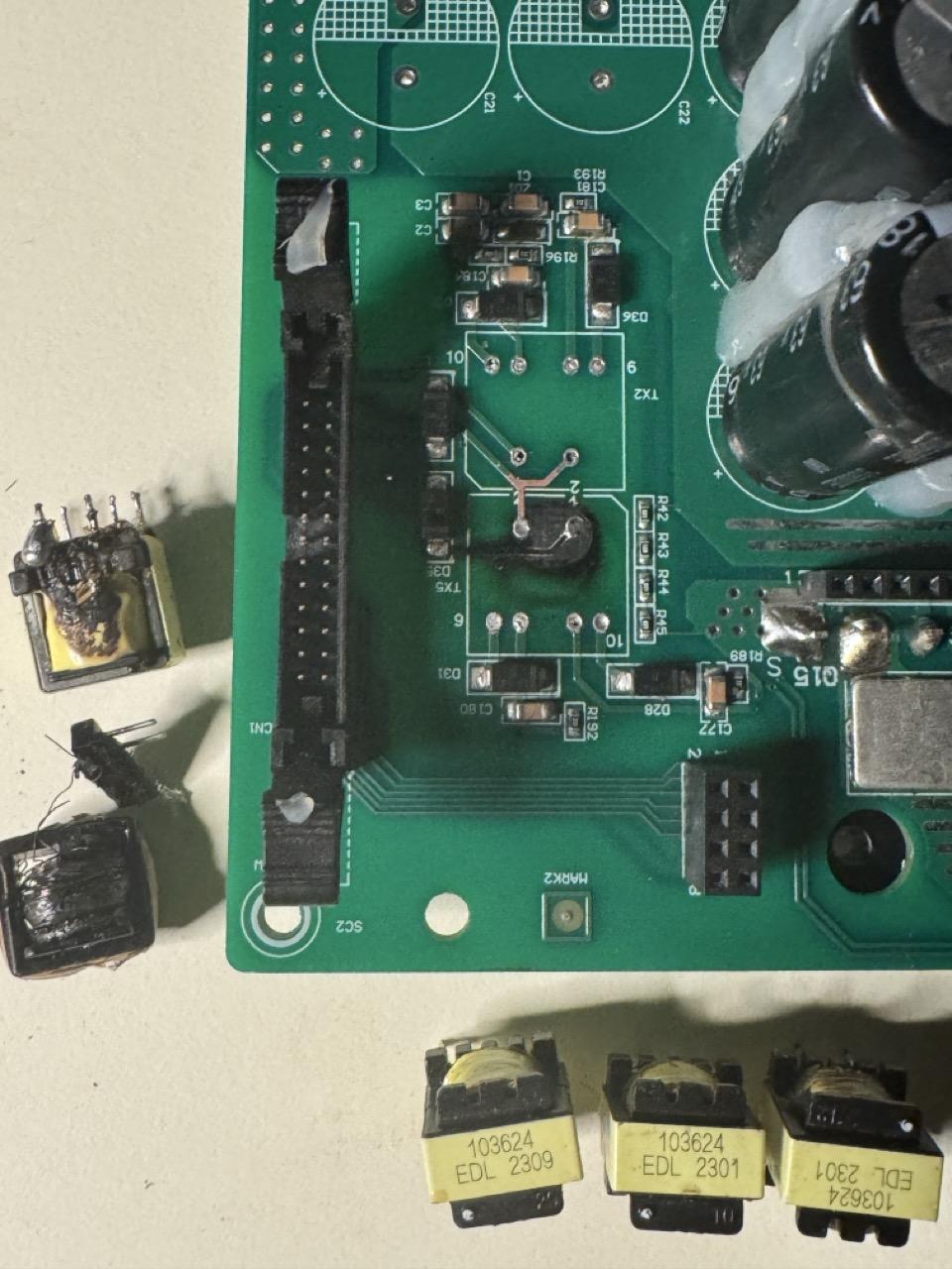
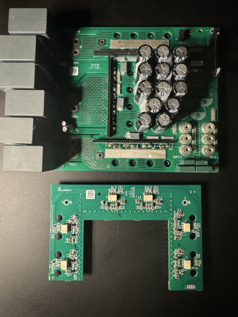
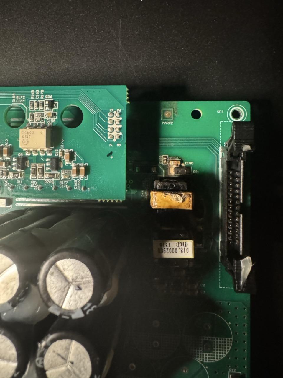
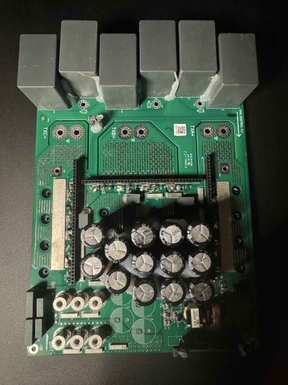
Good day Gents, It has been a minute since an update: The idea in this instance was merely to get the inverter up and running. However there are a few minor complicating factors that can make this impractical. Components availability is the primary area of concern, because a number of the components employed, are not off the shelf. Having exhausted a number of avenues as well as myself in the process. I initiated contact with Luxpower. I waited and waited until I eventually received a response. We have maintained a near daily contact, which ultimately resulted in the reception of two “DC Board Assemblies” and one LCD screen assembly. Circumstances are 1 on 1. However, I am of a strong belief that they will reasonably assist in any way possible, so long as the request(s) are reasonable. Brand new board assys /w drivers: Both are several months apart. From mid 2025 to late 2025. How do I know? The date code is on the xfrs. There are at least 3 separate revisions. Based on part numbers Brand new LCD assy Board being replaced (missing the two GDT) “isolation transformers) those had a date code of 2316 or the 23rd year and 16th month. (The cable retainer was removed from the original board and installed on the second new board) It broke in transit and took but a minute to remove and reinstall. This will be a very difficult week, and I am not 100%. In addition, I have not yet received the thermal grease priorly ordered, per manufacturer’s specifications. Next week I will provide a final update on a complete and fully functional hybrid Inverter, one that I have really grown to love and the little bits that sets it apart from other inverters, that I have not had the greatest of success with; longevity speaking. I can say this much: unlike most companies, Luxpower has owned up to its mistakes and has made a pledge to prevent future failures such as this. As a sceptic; I genuinely believe that they will. Having once worked in PCB manufacturing and later, IPC Compliance ISO 9001:2015 there are significant differences between the mainboards. Same parts different quality controls. ***Note*** I am not in any way affiliated with Luxpower or its subsidiaries; otherwise my inverter would have been repaired several months ago.


-
Hi, My apologies; unit 2, model nr: LXP-LB-US12K Thank you _Loch
-
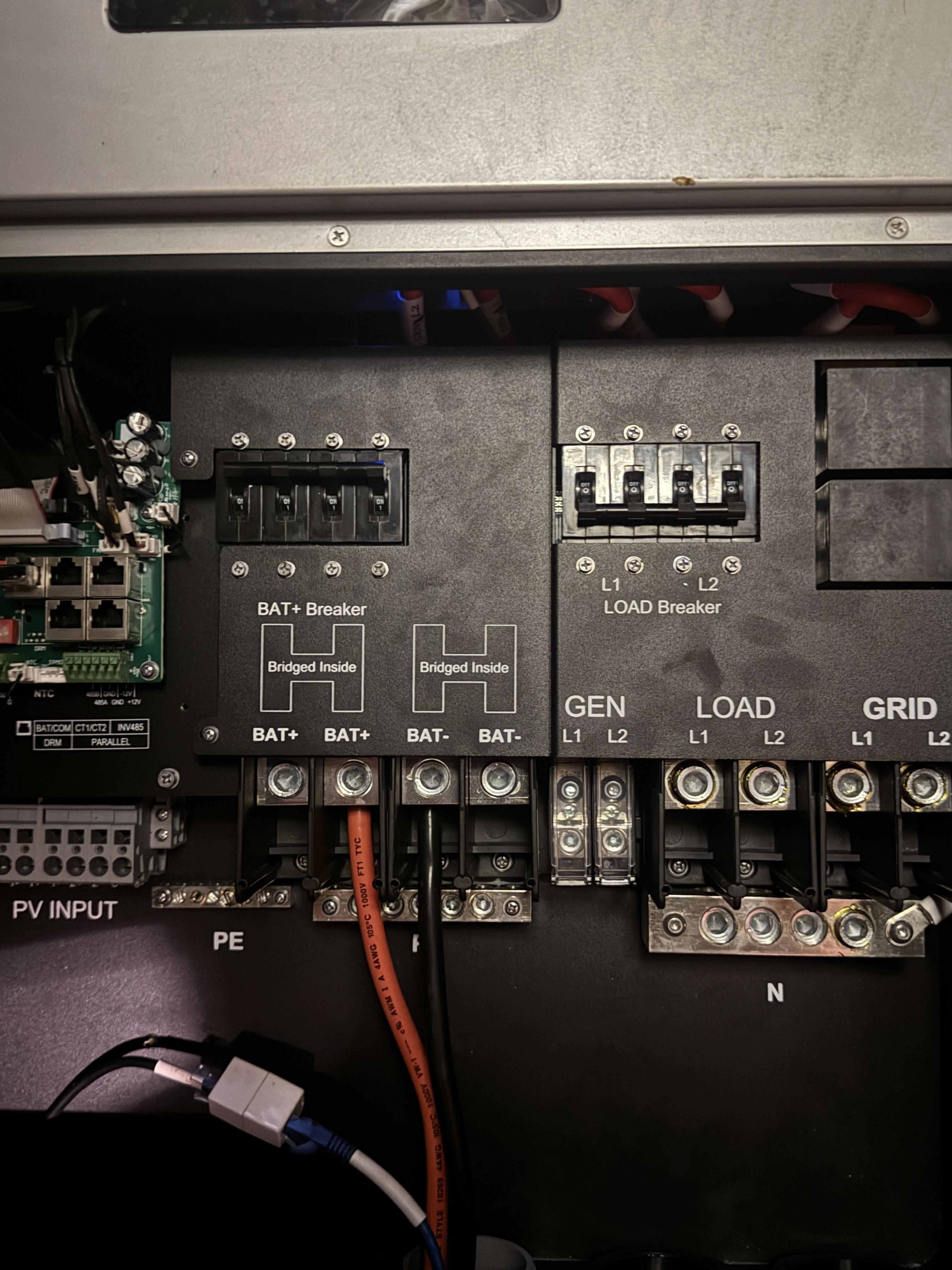
Good Day, It has been a minute since any further update status regarding repairing venerable Luxpower LXP hybrid inverter(s). There were initially two non-functional units, but nr. 1 of the 2 were “technically” repaired, if the RSD jumper counts as a repair. While repairs on unit nr. 2 started out relatively well, I cannot for the life of me locate suitable replacement gate drive transformers in the EE13 package. I am having difficulties just acquiring EE13 ferrites and bobbins to begin with. Unless my logic is severely flawed, i.e., an attempt to rewind a matching set of GDTs of sufficient mh, which appears to be proprietary parts to begin with: the manufacturer and part number(s) do not cross reference to any replacement whatsoever. At this point, for the sake of time, I am more than willing to purchase a replacement 3 level DC board from the Luxpower manufacturer or sales; and now a replacement LCD/CAPACITIVE touchscreen display, which broke when the unit slipped…[sighs] The screen driver board is still ok but is a replacement screen even available as a stand-alone part, without the driver board assembly? …what a cluster f… Unit nr. 1 is still powered up and producing power, it hasn’t been placed under significant load yet. It is more or less ready to be permanently installed. I did not see a practical need for an additional mcb panel, so a simple modification to unit nr. 1 was made: three strategically placed holes and 1 standoff was relocated by about 12mm for necessary clearance and the ground bus temporarily removed… The enclosure is more than cavernous as it is, and it just seemed practical if not convenient: just a piece of din rail and 4) 2pole DC breakers; the ground bar will be relocated later. Initially I did not want to turn the MCBs upside down, but the additional amount of time and energy to maintain an upright position, didn’t seem worthwhile; all existing PV wires had just enough slack to comfortably terminate to the MCBs. Being magnetic trip?, line and load must be oriented correctly. There are other options that I might explore at a later time that is not orientation specific but I am ok with the end results: If this configuration might be problematic, please let me know your thoughts on it. As for unit nr. 2 I have not conceded defeat; even if tech support leaves something to be desired: no response yet. If anyone knows where new or used parts can be sourced for these units, I am more than interested… TBD for now… thanks. The idea, in the case of an emergency, other than MCB protection indoors and outdoors is to wire the RSD shutdown in series preferably or via a plc, in a number of practical but discreet locations. One can never be too careful… _LochA bit unrelated: The red arrows indicate a problem, while the yellow are potential defects. A multi-positional ultra high resolution camera could capture the things that are not visible to the naked eye. For each production run, it would be programmed with gerber/BOM data/g-code, but the most m important aspect: defining the fiducials accurately as well as specifics such as rotational defects, polarity defects, component defects and so forth. The bga that was flagged in red is a significant defect, where the bga is incorrectly oriented. I wont elaborate on why, but they were removed and reoriented correctly. A miserable time consuming process. One, no problem, but 4 per panel times 20~30 panels is a disaster. What amounted to a change in procedure. 1 panel is inspected first before a complete production run. Even still… Each and every time. This was by far a tedium; probably the most boring aspect of this relatively small facility, yet one of the most crucial I grew to dislike it, but aside for a deadline, could move to another station; a floater. Eventually was taught how to operate any other station… a simpler time… Thinking about this, It made me wonder: when an inverter fails, what generally happens to it if out of warranty? I know that this definitely varies from region to region; though enquiring minds may find it a curiosity... I can only say that in general that here, a territory of the US, they are wastefully discarded and replaced with a brand new unit; I would say the waste is far greater on the mainland than here, locally. As far as the British side; repair is moreso the preferred route. Yes, I can speak for both, as a multi national. But for curiosity sake? Across the globe?
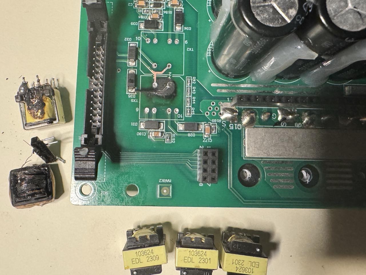
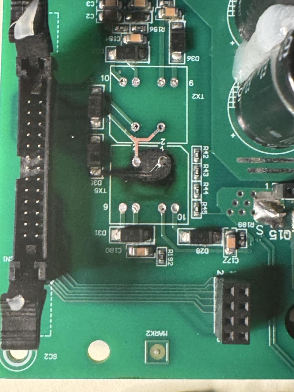
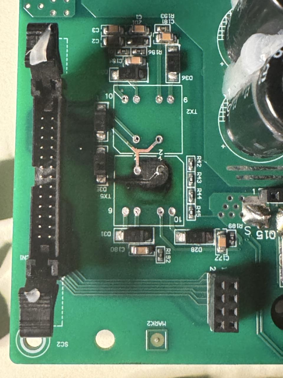
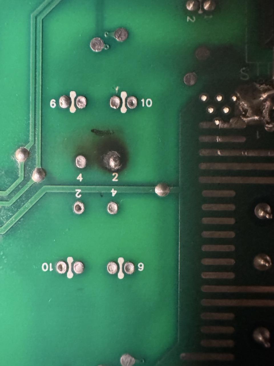
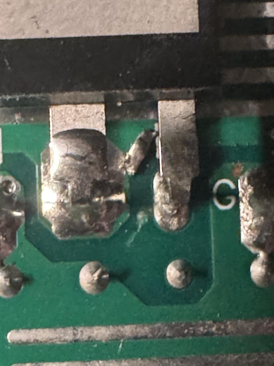
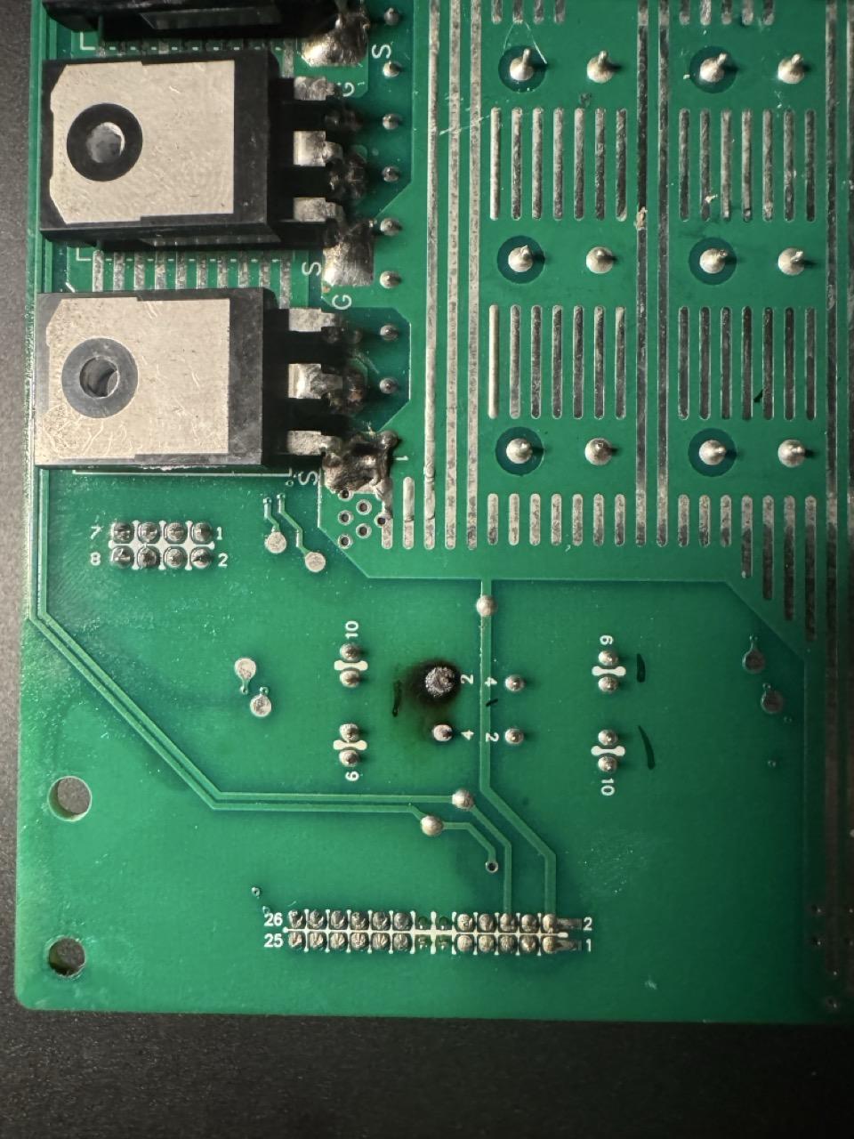
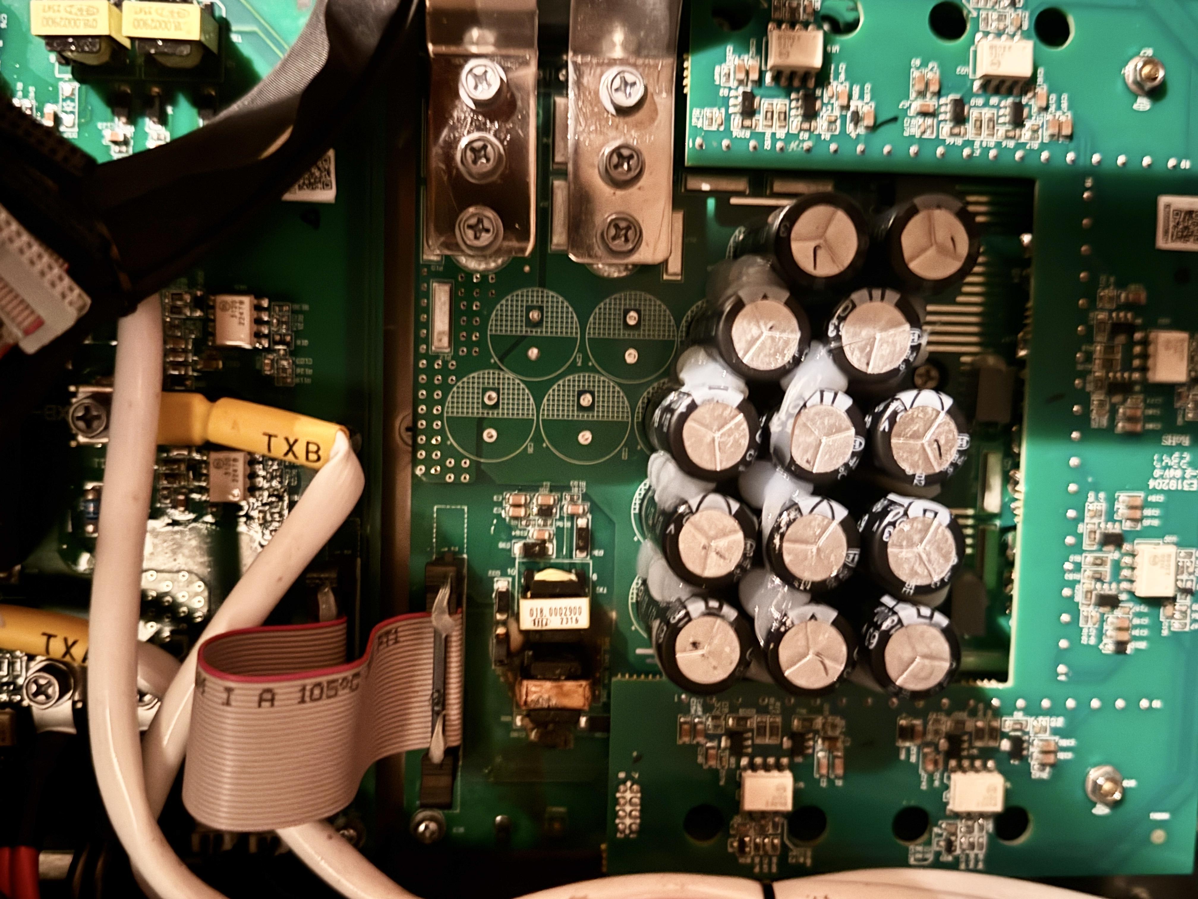
 Good morning, After sufficient testing and optical inspection, I am sufficiently satisfied with my findings: 1) All FETS are equal in value and there are no shorted gates. In circuit testing can be challenging when other components have an impact on them. Most tests were performed with an older 8846A, 6.5 digit bench meter. The diode function is especially useful ONLY because it can either check for leakage or other unusual conditions with insertion of 5V or 10v. A microwave diode, for example cannot be tested in this manner, not even at 5v; but it can be tested at 10v. Anyhow, resistance, capacitance and continuity were all valid. The objective is to verify uniformly across all 12 FETs in a number of distinct ways. Yes, connecting the curve tracer would have been much more precise but, not required at this point. I did not suspect a failed FET, but examined none the less for posterity sake. 2) All diodes around the GDTs tested ok, then tested again and again with fine tip leeds. No shorts, no open circuits; while mildly surprised; it is reassuring, where the mode of failure is quite consistent with the findings of the optical inspection, via an old M5 stereo microscope. I really REALLY love that scope, it was definitely built with purpose, down to every little detail; all precision machined. I do not mind the turret, eye pieces or objective lens attachments. It is so much nicer, in my personal opinion and experience of course, in contrast to the progressive magnification of the Greenough scope; while convenient, it is harder on the eye, with a quicker onset of fatigue. An absolute dream; those older CMO scopes. Albeit highly underrated... Rarely might I be so enthusiastic, but there is something about yesteryear, worth being passionate about; worth the added effort and dedicated enthusiasm. Moving forward, the smd resistor network, capacitors et al, tested good. Even GDT Transformer (TX2) is still functional. Preliminary Failure mode: a cold solder joint or joints connecting the failed GDT transformer (TX5). Narrative: over the course of non stop operation, that poor connection point(s) builds up resistance until ultimately it simply breaks down from excessive heat and inability to keep up with current draw and supply as pictured. I seriously doubt, but for posterity, I will verify the GDT driver, although if it did fail, by all logic, so should have the other GDT transformer; which tested ok. I cannot find my rework supplies; the burnt trace is detached from the PCB and has been temporarily tacked in place. Nothing major. The pad is still intact but the barrel/sleeve will be replaced and swaged over the reattached pad, for a nice solid connection. The burnt spot will be retouched in PCB green and sealed, as will the exposed traces. Now the literal problem: to source and equivalent set of GDTs. This is the most problematic; sourcing parts without actual or cross referenceable part numbers. As pictured, are some which are identical in package. Even the secondary is identical; unfortunately the primary is not. A difference of 1 ohn might not seem very significant; however the salvaged GDT is approximately 2.5 ohms on the primary. This means that the input voltage would be proportional to the output voltage based on the turns ratio. While the considered replacements secondary is identical, the primary @ less than half of the original, could potentially or rather likely be driven at a higher secondary, and this would most likely cause significant damage to the FET drivers. It would essentially operate at more than twice the expected rating. While there is a small possibility that it might function within range; it does not seem likely and I am not very willing to take that chance, unless tested independently with favourable results. But I Doubt it. Another possibility is: add a 1~1.5 ohm resistor of sufficient wattage to reduce the input voltage to a suitable output level, but a number of variables comes to mind… TBD Ideally I would love to find exact matches for purchase, but without any actual specifics, it is a difficult proposition at the moment, without any further research. If it were a steady state transformer it would not be an issue; I will have to pull out the function generator, assuming it will reach its operating voltage and given frequency; or operate it in reverse; 3.3~5 vin switched to extrapolate these required values, if the GDT driver is too ambiguous, but without researching the driver and its capabilities first, I am merely taking a pss in the dark. I am 100% certain that this board would have failed IPC-610 standards; I did quality control and rework a lifetime ago. Very very nice layout, but the through hole components; the cold solder joints, the foreign and stray residue? The residual flux? The outfit that did PCB manufacturing locally, was sold to Ametek and relocated its manufacturing facility elsewhere. It was the first time that I learned that circuit boards could be submerged in water, or ultrasonically cleaned. They were always scrubbed with a toothbrush after rework that is literally how it is done. There are no special tools for cleaning PCBs. The problem with kester flux or any other flux, especially concerning high speed circuits is that during the test/debug phase, if any residual is present, certain boards would fail under testing: the solution? Back to the wash station; which is similar to a dishwasher, but a very big one. The water was de ionized and heated, which de solved this water based flux, specifically for lead free solder. No tangent… just an observation… …still looks worse than it actually is; it is actually so much better than initially imagined. To think that this is the easiest part, if I can remember where I placed my kit. I am sure that most if not all of it is still good; the adhesives and the PCB green polyurethane… _Loch


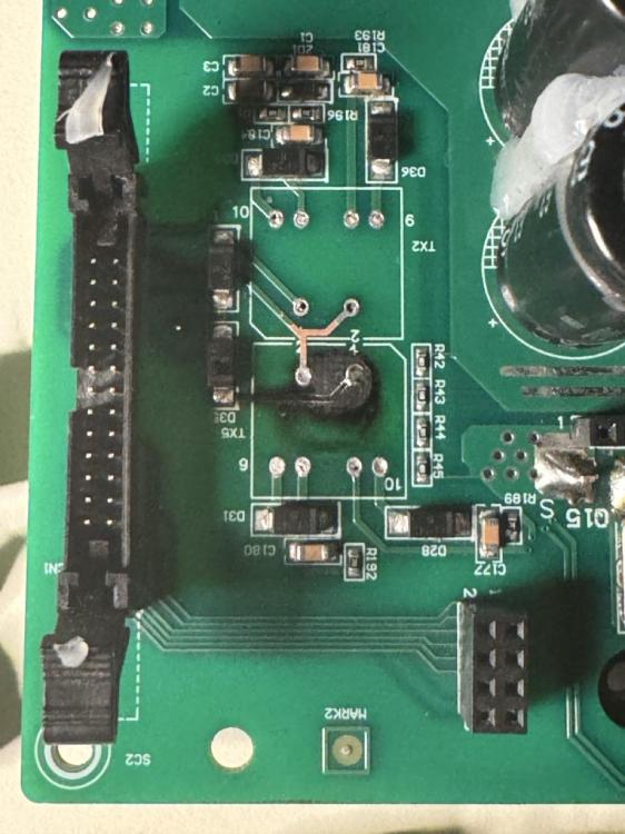
 Ok. so this is not at all what it initially appeared to be: the first thing that came to mind after complete removal was that it sort of had an uncanny appearance to the main board of a VFD. This is most likely a 3 level NPC board of sorts. 12 MOSFETS total; 6 drivers, which controls two MOSFETS in a pair. One high, one low. Both high frequency ferrite gate drive switching transformers share the same power source from the modulated driver output to common nodes (2), one node branches to both GDTs; the other node also branches to both GDTs but with two anti feedback diodes, to protect the GDT modulated driver from inductive backfeed to the driver, where the cathode is facing each transformer, presumably. Both GDT transformer outputs are common to all 3 levels: TXA, TXB and TXC and their respective FET Drivers. Bat + and - have been traced directly to the 26pin ribbon connector header, as well as a presumed feedback circuit from each level. Apologies for the poor explanation; not exactly my strong point. I Imagine that the unit would have most likely power up, but with a critical failure. It is generally good practice not to energize any device or circuit without basic verification, as this can lead to further damage and/or injury to self and others… Simply put, this is a deceptively simple circuit for my current repair knowledge library; or maybe not. Certain concepts and principles are slowly coming back to me (it’s complicated). However, being that only one GDT clearly failed; the truth is, that even without a schematic, which I am not certain is essential at this point, for this particular instance; where the sequential process of elimination, to repair are fairly straightforward. Next step is to check the diodes for a short circuit, where one seems likely. At least it is not a multi layer board ***correction*** this is indeed a multilayer board; the section in question is not affected by that fact. The relevant traces can be clearly identified with a backlight. After parts have been tested and removed, will then remove the “silicone” smeared over this area, scrub the board with isopropyl alcohol and a toothbrush, and repair the questionable traces as needed. At this point, there is really nothing to lose; I am certain that Luxpower would have this replacement board on hand, in the event that my repair attempt fails. But I am reasonably confident that this is an isolated incident; I have also noticed some other problem areas; which are more of a manufacturing issue than any thing else. Lead free solder can be problematic at times; A few cold joints, some solder balls and little stray bits of solder have been noted; perfect recipe for a short. On the reverse side, one leg of the transformer looks a bit overheated; which could suggest a cold solder joint, which ultimately failed due to excessive current draw and byproduct of heat. We shall see… It really does look worse than it actually is: after a little cleanup and some board re-work; she’ll be as good as new 😎 _Loch


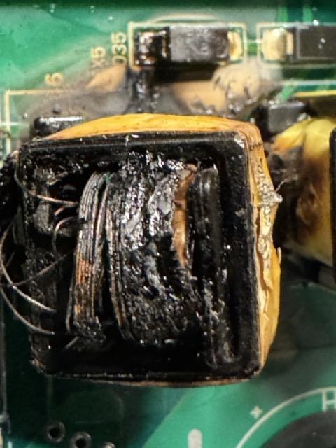
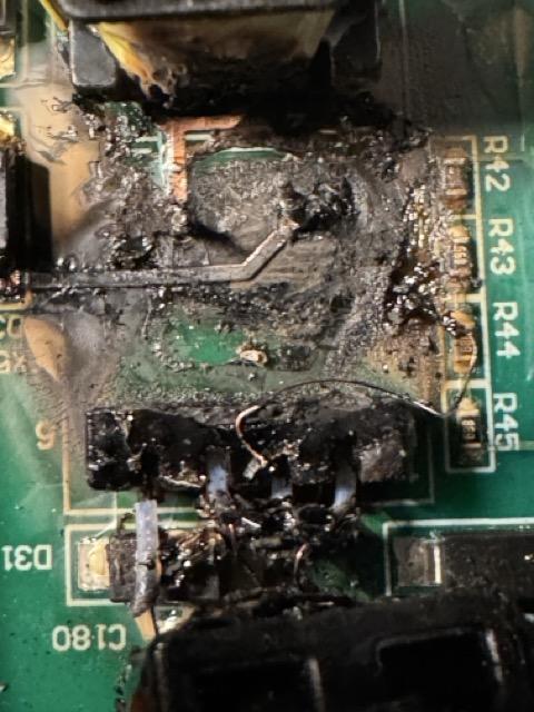
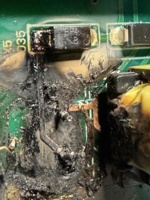
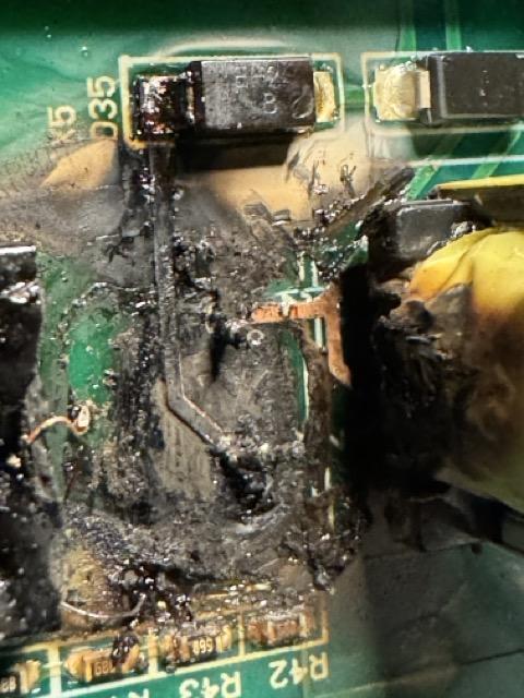
 Apologies; here is a better photo. _Loch
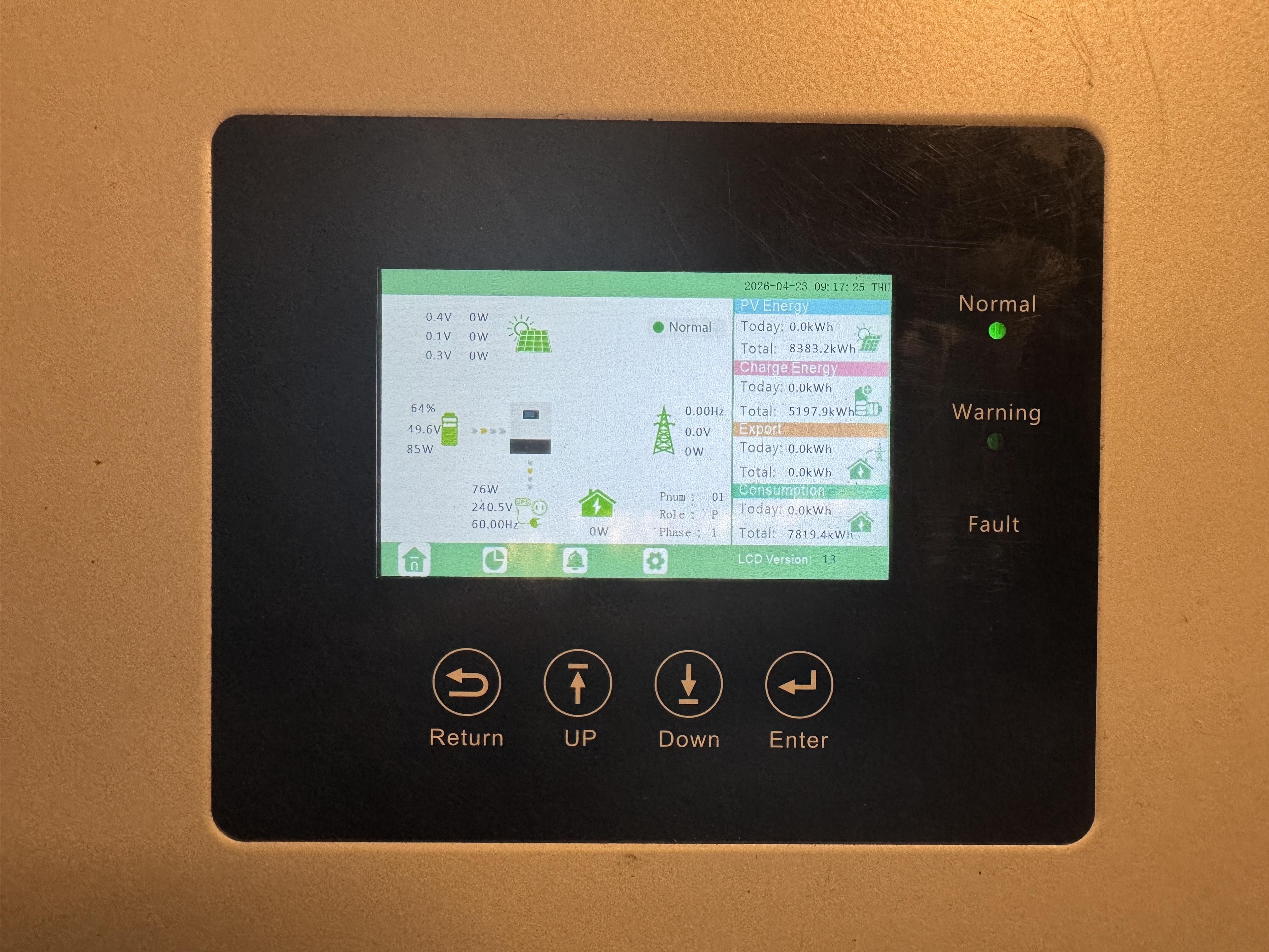
 This is the working unit; after figuring out how to make the older pylontech batteries communicate with it; I did not want to cut my Victron cable and opted to temporarily used a coupler and a small patch cable to figure out which one is (can h) and (can l); on this inverter, there is no (can gnd). Turns out that it is a straight through connection ONLY with pins 4 (can h) and pins 5 (can l). ***Correction*** Dip switch position on the Pylontech batteries does NOT appear to matter when using the CANbus port! Note: The initial sequence of operation may, at least to make it recognizable, but also, a few incongruities or glitches have been noted with the Luxpower unit; but appeared to correct itself after removing the CMOS battery for about 10 minutes or until completely discharged. The DIP SWs does not appear to have any effect whatsoever on “recognition” or any thing to do with the Canbus in general. My apologies; the very last thing that I want, is to perpetuate false information; but rather reciprocate the appropriate information. This thread might serve better in the |new to solar| section… The start up sequence of operation did appear to have a positive effect on what was intended: to make the older US series Pylontech batteries connect to the Luxpower inverter. I can only offer suggestion on what worked for me; nothing more. Being exhausted and dozing off in between, and a tangent later, is not proper for lucid conveyance of information. For this, you have my apologies. The sequence of events that appeared to establish CANbus communication was: 1) fabricate or acquire an appropriate communications cable. In this case, the Luxpower LXP series inverter, and the pylontech US series CANbus utilize the same twisted pair; pin nr. 4 is CAN H and is the striped-blue wire. Pin nr. 5 is CAN L and is the solid blue wire. Both ends are configured exactly like this. Note: My initial problem was defining pin nr. 1 as a reference. The manual(s) are a bit ambiguous, or perhaps it was just my misunderstanding. This is determined from the contact side and NOT from the keyway side as recently learned. Not so interesting, the very opposite was the method and way I was priorly taught. The problem with this method is that the terminated pins in this instance, are in the reverse order; which presumably may cause damage in some instances where power is also transmitted. Networking 101, I presume… 2) Where DIP SW position is irrelevant, to the best of my revised understanding; all DIP switches on all Pylontech modules are now in the off position, by personal preference. It is recommended to power off all batteries before making these changes. Connect only the battery side of the communications cable and restart all batteries. 3) Set the inverter to lithium, and the following drop down menu to: nr. 2 lithium (Pylontech). 4) Restart or power on the inverter; it is recommended to leave the load and PV switch off, for the time being. After the inverter has fully booted and the main screen is displayed then plug in the other end of the communications cable. Recognition took about a minute or so. Note: this method worked for me, where I could not establish communication any other way. Mileage may vary, and perhaps there is another way to achieve successful communication between inverter and battery BMS via CANbus. 5) If successful, the inverter will not throw a comm error alarm. This can be ascertained within 2 minutes. To confirm, under stats and then battery, It will show the correct SOC/SOH, BATT CAPACITY, VCELLMAX/VCELLMIN as well as a VCHARGE/VCUT OF 53.2VDC/40.0VDC. These are set to 52.5VDC and 44.0VDC respectively, for my specific application, but also per the manufacturer’s recommended operating range. 6) Older Luxpower inverters are pins 3 and 4; this was a bit confusing because there are a t least one factory datasheet in circulation that appears to be misleading. The colour of the dip switches changed 3 times: “V1 is red, V2 is blue and V3 is red”. V2 and V3 utilize pins 4 and 5, but V1 utilize pins 3 and 4. <sighs> when in doubt, the manual specific to the unit is almost always correct… 95% of the time, unless a new revision, or software update states otherwise. _Loch
 …It was my sole intentions to say (or rather demonstrate to a few associates of mine) that solar energy can be affordably had; even at a sight budget. Not all equipment has to be brand new, and that a system can be designed to be expanded upon. I know that it is possible, but I chose the wrong methodology to convey this 😑 plus this does not help the cause. Yes, this it is very repairable but I can’t say that, en masse; electronics repair is just a former hobby at this point; where in the past, most consumer electronics were repaired NOT replaced as in the present. There are no repair shops locally, and shipping it off to the manufacturer is not an option. Warranties on these units are seldom honoured. If so, the local retailer on island would have already had them repaired or replaced under warranty, presumably, and not sell both units for next to nothing. The other unit had a problem; it did not appear so except the RSD alarm would not go away. I would not consider that a problem, as it powered up without any trace of the magic smoke. The solution: its safety jumper was in the terminal block of the dry contacts in the wrong place; a short piece of red wire with a tag that reads: “Remove it in installation”. Source of repair: The installation manual which states to put it back after installation. Time spent troubleshooting: about an hour. I grew up learning not to be wasteful regardless, and if something is broken; fix it rather than discarding it. For a small oversight, that Luxpower unit is fully functional. The other unit… that one was a bit of a surprise, I do not even see any tool marks on the hex allen head lugs. After removing the breaker/relay board and the battery breaker, did I catch a whiff of the magic smoke 😑 then the upper circuit board, and there it was 🤬 Until I remove both transformers; the top to source a suitable replacement, the bottom which visibly is done or rather “well done” bad pun I know; test the diodes, resistor network (not likely but relative to potential above ground ) and presumably IGBTS or MOSFETS below, as well as the rest of the relevant circuitry, I can not say with certainty what caused this: something as simple as reverse polarity improper input or, a software based feature that I am not particularly fond of, regarding toggling the GEN input to a smart output or a point of AC coupling PV... Because this is the immediate DC board to the batteries, all AC sources are called in to question. In general, most if not all control circuits in this unit are DC. Looking at the relay board and breaker for LOAD , I know that the primary control voltage is 12VDC since those relays are activated by 12VDC, which controls the GRID and PASSTHROUGH: 12VDC coil and 200A @ 830VAC. (The GRID input can be toggled to a GENERATOR input). The FPGA control board, touchscreen comm board and control circuits are DC. I am fairly certain that there are also a 3.3?, 5, 24 VDC rails. Note: I am pleasantly surprised to see a number of high quality components in this unit: rubycon capacitors, Texas Instruments FPGA; airpax style breakers, big solid lugs and “ground planes”, heavy high current busses, an abnormally large amount of filtering /smoothing capacitors, lots of opt coupling and isolation, which really begs the question? WTH happened? How was this accomplished? The diodes appear to be rectifying some AC source via a small step down transformer to DC, which is likely coupled to smothing capacitors to power up the control circuits; these hybrid units do not like to be operated without the batteries connected; it is not impossible but the manuals for most inverters have a startup sequence, and a shutdown sequence. Not that I am stating something that everyone is likely more familiar with than I am. What I am not fond of is that the software does not forcibly disable toggles that would otherwise conflict and cause damage, which is clearly stated when selecting the smart output option; rather than simply disabling or deselecting the conflicting commands. But then again, the input/output values can be zeroed out for the most part but it can be too easy to make a mistake even after reading the manual in detail. I am not impervious to mistakes; I knocked out my MPPT charge controller with reverse polarity, even though it has reverse polarity protection: just not while it is loaded with PV energy; but fortunate to have a backup while I repaired it; it blew a MOV but not quick enough before it blew an IGBT. The shorted IGBT caused the charge controller to keep rebooting in a circular. It functioned fine after removing the failed IGBT (there are 6 of them in parallel) so in effect, it only temporarily reduced it’s capacity, until all 6 were replaced for uniformity and good measure. Anyhow, I do not believe in waste; it is not trash or a spare parts unit (unless proven otherwise in the unlikely probability). With that said. There is a power supply much like this on each board: the inverter board, the MPPT board, this main DC board and so forth. To be continued…
 Hello It appears that there is so much information regarding PV that I truly had little to no understanding of. Of course this is still a bit of a steep learning curve, but I think that the basler principles and functions are better understood. I was always of the opinion that the higher the current output DC the better; contrary to, it seems that higher current output, can lead to a shorter system lifespan, as opposed to a higher voltage system which is more predictable and constant, as opposed to a higher current, which may be more prone to fluctuations throughout the day. At the end of the day, power is power (total watts) no matter the configuration. After a bit more research, (x) S1P, (x) S2P, or even expressed as: (x) P2S; although the prior is a cleaner expression. I am of the opinion that higher wattage panels are a bit more difficult to configure and where shading can be a bit more problematic opposed to a comparable array, utilizing lower wattage panels. Besides the advantages in a more flexible configuration; subtracting the bifacial component, which two panes of glass have a tremendous effect on weight, with little to no additional gains, at least in my region. I now know why they have been in stock for such a long time, with the remaining panels being still available. Originally I bought 8) 440w panels; and by the end of the week, when I was “satisfied” with the initial layout, factored weight, cable routing and “power calculations” all 440w panels were already completely out of stock; ALL 12 PALLETS!!! I could not believe this; it seemed too incredulous at the time. What I needed and wanted was one panel style; having read a vast number of posts regarding mixing panels. sure, more 440s would eventually return to stock, but in a different format or form factor. I was then told about this 1 pallet of 635w panels that were in stock; just 1. My question was how long would they remain; but assured that all 31 panels would be available for sale. It sounded perfect, but naturally being a bit wary, the decision to purchase the 20 at once, really more than intended, seemed like the safe and sensible thing to do. In a way it was, because the remainder 635s are all still available for purchase. But I now know why: no sensible individual would ever put 20 to 30 panels 1400 LBS plus 700LBS (over 1 ton) or ironically 635kg plus 317.5kg, NOT including racking, on their existing roof, unless it was priorly reinforced or constructed to handle that much additional weight. Having once lived in a place where it snowed heavily to the point that the front door would be frozen shut at times; where the water pipes occasionally froze shut even when insulated and wrapped with pipe heaters; when the smart thing to do was simply leave the faucets open just enough to discourage blockage or potential damage from expansion, and presumably where roofs are built to intentionally withstand that extra weight, without caving in; assuming that you would clear it off after a snowstorm; both ends of the spectrum still would not favor that added weight on any roof unless in a commercial application, but preferably a low mounted installation, or a carefully designated “roof”. Balconies, galleries or porches are intentionally designed, “engineered” and constructed “to separate” from the main structure, without significantly damaging the main structure in the event of a serious hurricane: the above listed “appendages” while unified in appearance, are completely separate roofs in a heavy, pegged post and beam type, arrangement. The independent ring beam is attached a beam that is attached to the main structure with square cut nails; now with a few reproduction nails and are meant to break under extreme conditions… the existing was in need of some repairs and additional reinforcement. To my relief it has weathered the tests of time quite well; being that the square cut nails were hand wrought and intact and the planking, and the the rafters were still “heartwood” pine; the proposed repairs were sympathetic; to graft and splice only the minor section of rot with green treated lumber but it was stressed over and over again by the contractor that it must give unless I want the easterly “wing” to be damaged or worse in a likely scenario. With shallow pockets, we scrapped the idea of The “glass ceiling effect” that the solar panels would impart mostly because of the already unforeseen exorbitant costs, often associated with DIY projects, I am very appreciative of his lengthy explanation, as well as his expertise and knowledge in construction, as well as his bright enthusiasm, where he showed me some roman numerals carved into the rafters where short sections of planking were sectioned from “a single piece of wood of that length ””indicating non dimensional lumber and confirmation of age based upon the cross-hatched saw marks and forged nails” I should have taken some photographs, but I am sure that he did. I know that this is a power forum, not exactly a construction forum. If anything that I have learned during this process is: the cheap becomes extremely expensive very quickly, especially during these times. _LochHi, @TaliaB I am primarily located in the U.S. Virgin Islands; formerly known as the Danish West Indies (as of 1917). Yes you are correct; a part of the Caribbean; Lesser Antilles. Thank you for that bit of information. So if I understood correctly, the bifacial component has no significance in overall design; at least not in this region? _Loch







Account
Navigation
Search
Configure browser push notifications
Chrome (Android)
- Tap the lock icon next to the address bar.
- Tap Permissions → Notifications.
- Adjust your preference.
Chrome (Desktop)
- Click the padlock icon in the address bar.
- Select Site settings.
- Find Notifications and adjust your preference.
Safari (iOS 16.4+)
- Ensure the site is installed via Add to Home Screen.
- Open Settings App → Notifications.
- Find your app name and adjust your preference.
Safari (macOS)
- Go to Safari → Preferences.
- Click the Websites tab.
- Select Notifications in the sidebar.
- Find this website and adjust your preference.
Edge (Android)
- Tap the lock icon next to the address bar.
- Tap Permissions.
- Find Notifications and adjust your preference.
Edge (Desktop)
- Click the padlock icon in the address bar.
- Click Permissions for this site.
- Find Notifications and adjust your preference.
Firefox (Android)
- Go to Settings → Site permissions.
- Tap Notifications.
- Find this site in the list and adjust your preference.
Firefox (Desktop)
- Open Firefox Settings.
- Search for Notifications.
- Find this site in the list and adjust your preference.