L_D
Members
-
Joined
-
Last visited
Everything posted by L_D
-
Hi there - quick technical question. Both strings state 13A PV input current. I have 605W Canadian Solar's 6x PV's on one of the strings will give me 3630W / 249V = 14,57A The other string will have 5 panels, same DC current. My question is twofold: 1: Will this inverter clip the excess dc current? 2: Will Sunsynk honour the warranty if the inverter board were to fold with this known dc input? LD

-
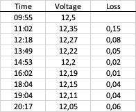
I did exactly that before reading your post and the BMS jumped into action once the PV source was added. The Sonoff's remain nicely powered and I am running a full day test to see what the actual consumption/load is on the batteries every hour. So far the voltage drops with between 0,05v and 0,08v per hour with one unit connected. The Sonoffs are going to power my Hunter DC solenoids. <<Update 13 Aug>> So I connected the batteries and tried to measure every hour. The usage is well within the reach of these three lithiums. Happy days 😁
-
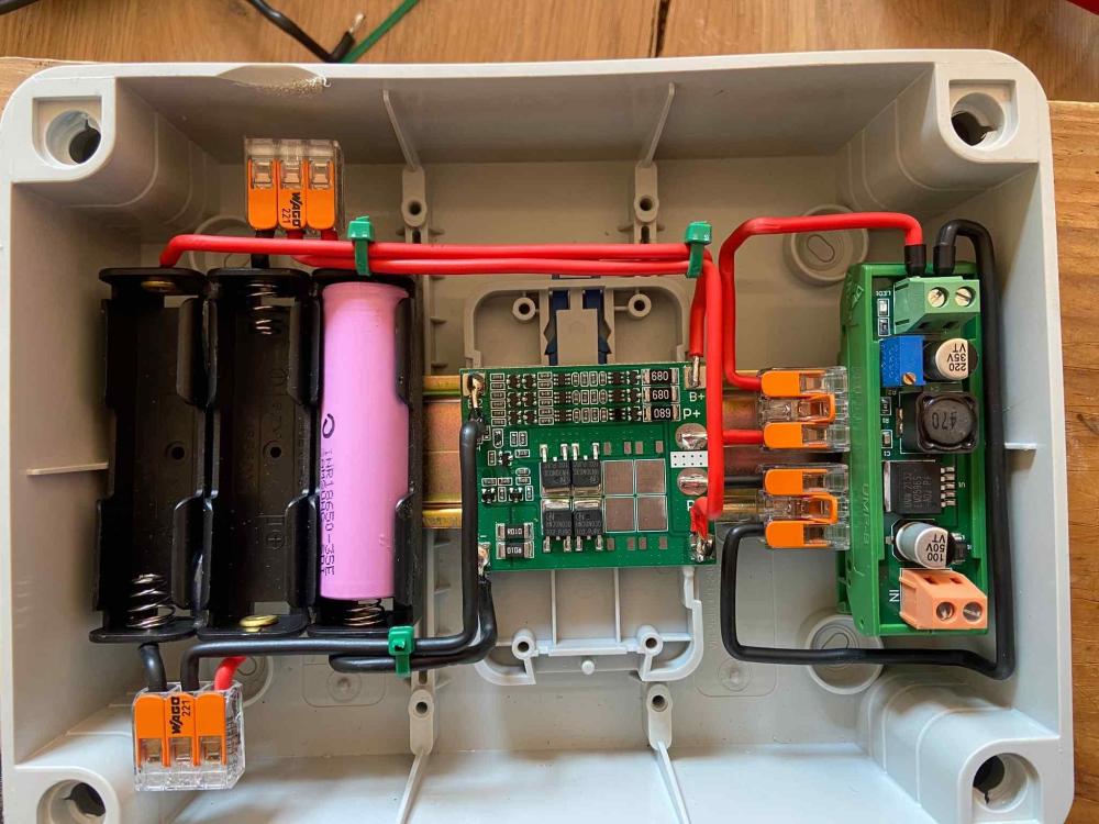
This is the battery power for two Sonoff 4CH R2's. The charging voltage coming in is via a 18W PV panel that is regulated by a voltage regulator trimming voltage down to a constant 12,6V. The Sonoff's DC input range is 9-23V. The Sonoff's power consumption in standby mode is 0.5W. @stefan44 when I disconnected the voltage regulator I got current on my BMS load (P+ & P-) This does not make sense at all because the regulator is not connected to any pv input and the output of the regulator is not generating any input power. I am using this regulator.
-
Well spotted @HendrikBigChief!! I brought the mosfet issue under @Robofactory's attention , their product image displays 8 mosfets, yet mine only had 4.
-
This BMS goes up to 25A. I am only going to power two Sonoff 4CH R2's that use very little power. This BMS should be fine right or should I get something else?
-
Powered all three batteries to 100%, issue persists 🙈
-
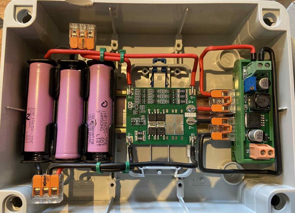
Hi @HendrikBigChief I swopped B1 & B2. Same problem persists. Load is near dead on the voltage. Any ideas? Read on a post that a BMS will turn loads off if there is a cell imbalance, more specifically if the cell voltage is below the "Allowed to Discharge" setting. Popped the 18650 into the normal USB charger and saw they were running @25% or less. This could be the cause. Charging al three up to 100% and giving the thing another go after that... My BMS Values: Overload Voltage: 4.25 - 4.5V Charging Voltage: 12.6-13V Working Range: 20-25A Operating Temperature: -40 C ~ +50 C Immediate Stream: 35-40A No Load: <30uA
-
🙈 SUCH a rookie mistake, thank you @HendrikBigChief for pointing that out, I assume the BMS wouldnt have any suffered any damage due to this. Will redo this and give feedback.
-
Hi forum guru's I hooked up three 18650 to a HX-3S-FL25A-A three cell BMS. Wiring diagram with the unit showed this: and my project looks like this post soldering and wiring: I get nice clean voltage onto B+ & B- when testing with my multimeter, however when testing the load/input (P+,P-) I get 0,1V. It seems as if the voltage does not flow all the way through to my load. My wiring was done as per the spec for B1 and B2. Any guesses as to why this is happening? LD

-
Took my neighbour up the street's stats from his setup that is pointing N, E & W on separate MPPT's. The drop in efficiency if you take North as optimal with no loss is larger than 15%. East was 40% and West 47% which is in line with the azimuth angle at 19 degrees.

-
What is the % drop in productivity from North to East and West in SA?
-
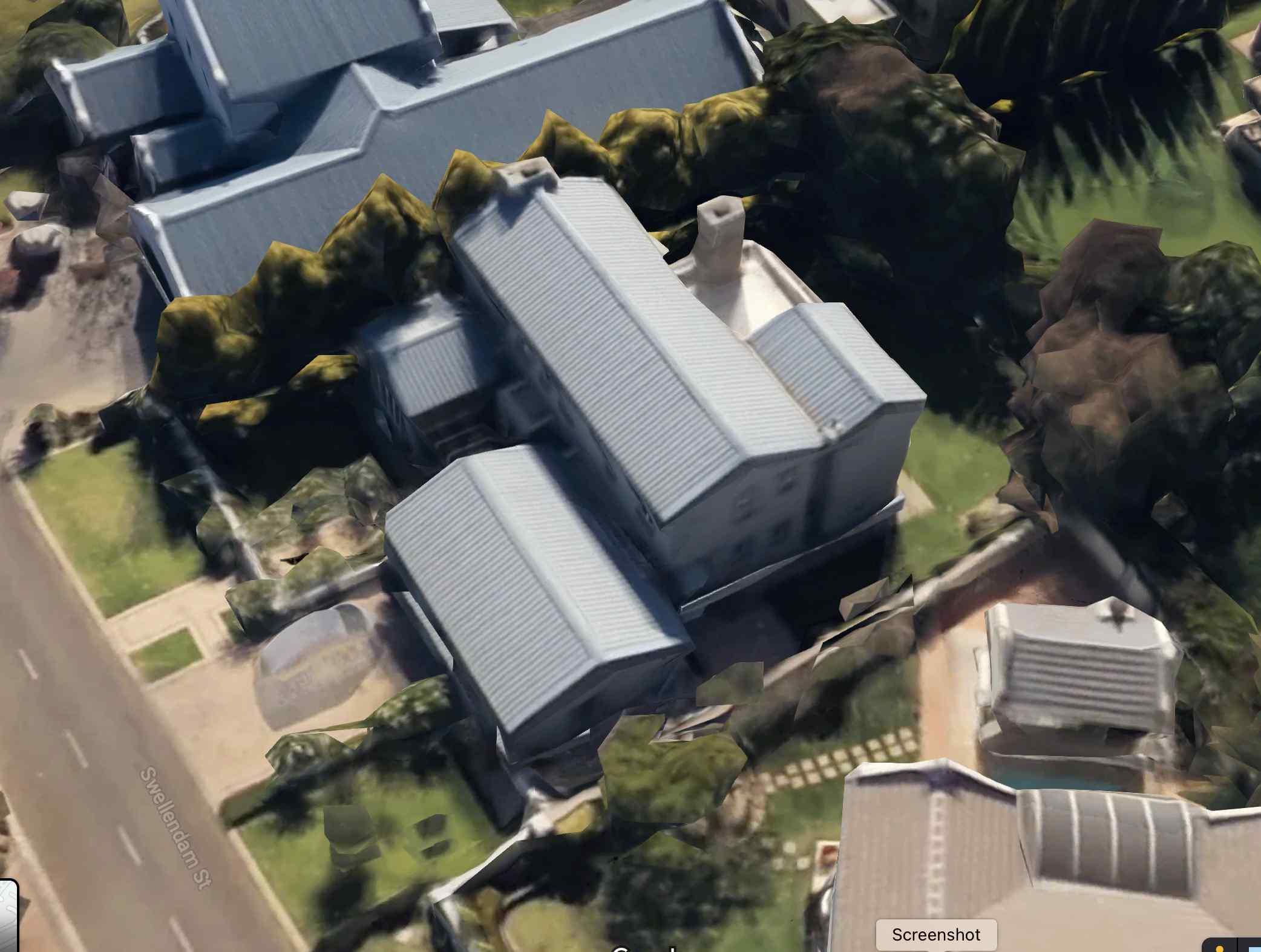
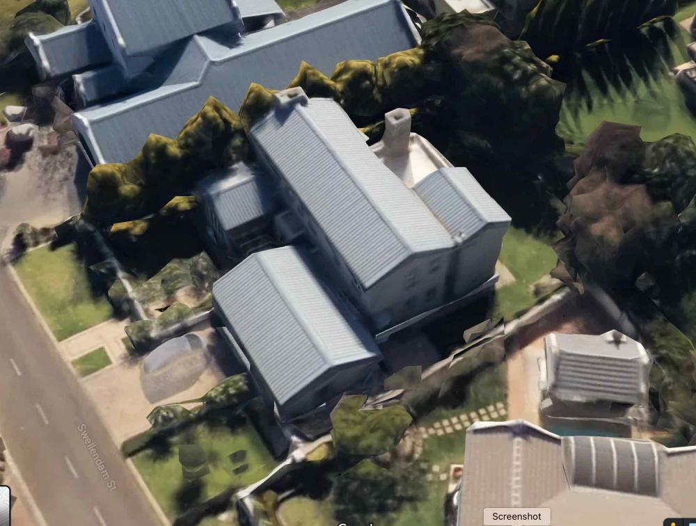
Given this house of my friend that is not facing North, what is the best configuration - all 10 panels West, or 5 East and 5 West on separate MPPT's? He has x10 Canadian Solar 605W's Given the fact that his optimal azimuth angle is slightly east it makes more sense to put all 10 panels on the eastern side of the second storey?

-
To @GreenFields, @Kilowatt Power, @Scorp007 and anyone else I might have missed, thank you very much for the very insightfull information on the panel efficiency and what I should install given my setup. Your contributions are pinpoint and valuable!
-
Hi scorp, the Canadian Solar spec states -0.26% for every degree more or less than the optimal 25 degrees? Why are you saying an increase if the temperature dips below 25? My total VOC at zero degrees sum would then be Total VoC (415) * (1-(24*0.26) =415 * 0.937 =388.85
-
Are these low temperature corrections applied to Canadian Solar Hiku7 panels? Different panel manufacturers and models behave differently? Given the concern this is what my VoC would look like for 10 vs 9 panels: This is some preliminary info I could get on my panels: Solar panels are tested for their efficiency at 25°C. The ratio of the change of electrical performance when the temperature of the pv panel (or array) is decreased (or increased) by multiples of 1°C, relative to its quoted 25°C STC reference temperature. So given the Candian solar spec, my VOC would decrease with 0,26% for every degree lower than 25°C, and not increase as you have stated in your reply?


-
So the best for my setup given the Growatt limitations (1MPPT, 18A max, 120V~430V) would be to connect 10 panels in serie to a 1 string combiner box. That gives met 6050W, 17.2A and 415V 🤷🏼♂️
-
The electrician says he connects two strings of 5 into a combiner box with surge arrest and fuses. He says he has never connected 10 panels in series, always does two balanced strings. Can you connect two strings into a combiner box without exceeding the current?
-
-
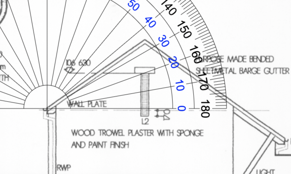
Panels are facing direct North with a 35 degree pitch
-
Thank you @TaliaB, VOC makes much more sense. I will stick with 10 panels that will be within spec without melting my inverter to a crisp.
-
....but yours is different firmware and internals. You cannot load 113 on a 40.06. Growatt mistakenly gives all these different inverters the same model number.
-
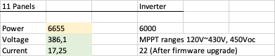
Here is my Firmware version @zsde I saw on this thread that a firmware upgrade takes the limitation to 22A as you also said zsde. I recall that I once logged a call with Growatt on the 040 series and asked what is the latest firmware. It is 40.06, 41.06 Here is the link that Growatt gave me to download the correct firmware. It is maybe worth my while to upgrade the firmware given that my panels in serie will be so close to the 18A limit. I have 11 panels and if connected in series would look like this: Does anyone in the forum have any practical experience with overloading of power in this inverter and how much unnessecary power the inverter will clip? I have reached out to Growatt @ [email protected] to also get some input on the proposed install. Add in a conservative efficiency loss of 10% then gives 5989W of power. "When designing your system, a good rule of thumb is that your solar panels should be 10-20% larger than your inverter. In hot climates, that can be extended up to 30%, due to greater efficiency losses from heat." Link Taking the above you then take the power minus efficiency loss (5989) divided by the maximum PV input (5500W) which gives you 9%. I have seen many comments stating 6000W as the input max in which case this gives me a 99,8% PV array match to the inverter. "Typically at solar noon (maximum solar irradiation), a PV array will have its STC output power de-rated by between 20-25%, due to the array operating above 25ºC." Link Given the type of loss from this statement at 25% will give 5656W.


-
Yes they will all face North. Series is the only way to hook them up as suspected. One last question to the forum though. Growatt states max current at 18A and max voltage at 450VDC, that gives you max power of 8100W as opposed to the max 5500W they are stating. My gut feel is that this install would be safe installing ten 605 panels in series giving power input of 6050W given the fact that my current would be 17.25 and my voltage would run at 351V. Current and Voltage are the two values that should never be exceeded on the inverter hardware, right? When the Aussie forums refer to overloading then they are implicity referring to excess power/wattage that the inverter can handle (obviously up to a point).

-
This is the suggested wiring from the electrician. Two rows in series, hooked up in parallel. The current under this config would be too high for the inverter, should all ten not be hooked up in serie to keep the current at 17,25A?

-
So the Growatt 5000ES spec show that max PV array power is 5500W. So the max could then only be nine 605W panels giving you 5445W? Max Open Circuit Voltage is 450VDC. Nine panels would give you 373,5V which is well within spec. https://onlineshop.gcsolar.co.za/wp-content/uploads/2020/08/5Kw-48V-Growatt-SPF-5000-ES-datasheet.pdf If I were to add 10 panels it would give me 6050W and 415VDC. Can one exceed the Watts (in this case by 9%) but keep the operating Volts within spec? LD