Janma
Members
-
Joined
-
Last visited
Everything posted by Janma
-
@Ursi About the fuse, you only really need one on the string. The reason is that the + and - wires of the string will always carry the same amount of current (Amps). Think of it as a closed loop that start of at the panels, goes through the combiner box to the inverter and then back to the combiner box, back into the panels. The current that originate in the panels always goes back into the panels. A fuse will blow (stop current flowing) if the current through it gets too high. When this happens the current will stop flowing on both the positive and negative wires. If you have two fuses, one on the positive and one on the negative wires, one of the two will blow first and stop the current from flowing through the other. Regarding the SPD, It is a very good question. You had me thinking for a long time. I am no expert with this but here's what I think. (Someone please correct me if I am wrong) A single pole SPD has two terminals. The one attaches directly to earth, the other attaches to a "live" wire that you want to protect from surges. If the voltage differential between the "live" terminal and earth reaches a certain value then it will "arch through" and allow the surge potential to dissipate to ground via the SPD (rather than your inverter or other expensive equipment). If one of the wires (negative or positive) is grounded INSIDE the inverter then the voltage potential on that wire will always be the same as ground (0V). The voltage on the other wire will fluctuate. I suspect, that if this is the case then you would only require a single pole SPD. If on the other had you have a floating DC circuit were neither the positive or the negative wires are bonded to earth (inside the inverter/charge controller) then you would require a dual pole SPD. NOTE: Don't ever ground your DC negative or positive wire unless the inverter/charge controller manufacturer explicitly state that you have to!
-
@Kloon I was exactly where you are now. I also did not know what size inverter or even type of system I should get. I was unsure if I should cater for 6KW peak demand. I was conserned that it might not be enough. I saw the prices of 10 KW systems and they were not within my reach. But what would happen if I went smaller, would the smaller inverter work or would I have constant overload/trips? My Prof at varsity use to say that "If you can not measure something you can not control it." Knowing what your usage is takes a LOT of guess work out of the equation. What I would suggest is move into the new place. Get your solar water system, gas stove in place first. Invest in a energy monitor. Let it run for a couple of months and then use the figures to do proper sizing of your system. At this stage you have so many "unknowns" about what your consumption will look like that its very difficult to know now what size system would be best. That said you are already on the right track. Read as much as you can, research all the inverters and types of system, BiDirectional/Hybrid/Grid Tied etc. Look at the different brands and find out where to get what at decent prices. Once you have have the figures about your actual consumption to get the correct sizing is much easier. About energy monitors. Look at one that you can download the data onto a laptop/pc. When I first bought one (the cheapest I could get at the time) it only gave a small bar graph on a screen and only kept history about total daily/monthly consumption. It could not give me peak usage etc.nor could I download the data onto my laptop. The second monitor I bought worked a lot better. I could download all the data onto my laptop. See the peak utilization etc. But as I found out this week it does not give me information about the power factor.. but thats another story. So now I have to get a third one.. Maybe save yourself the expense and get a good one from the start.
-
Hi DeepBase9, It depends on the type of system that you have and what it does with the power it gets from the panels. If it converts it to 220-240V AC directly it typically needs voltages quite high, typically these type of systems require Voc of the string in the order of 500 - 550 Volts. If the system converts the power from the panels to say 48V DC it typically require the Voc of the string much lower (in the order of 100V). There are exceptions. The key is to stay within the specs of the device you use. The larger the difference between the input voltage from the solar panels and the output voltage to the batteries/grid the more losses/complexity in the conversion process. I'm sure others on the system can give you more details about it. My system is Grid Tied so it converts to 240V AC that is why the Voc of the string is much higher than say a typical MPPT charge controller that charges a 48 Volt battery bank.
-
Also when water boils it can deposit minerals that could start clogging things up. Just look at the inside of your kettle and you can normally see the calcium deposits. The same thing would happen in the geyser if heated up excessively.
-
Hi Ursi, I have a setup simular to yours. 13x 255W panels on the roof all in Series. Voc of the string at just below 500V. I also considered building my own combiner box that include three things (all rated at over 500V). 1. DC Isolator (dual pole) 2. DC SPD 3. Fuse holder with fuse The DC stuff rated at 500+ Volts are not that easy to source. You can't just walk into any shop and find it. There are places you can find them though. When you find them they are a LOT more expensive than the AC breaker etc. Since, I have mostly Microcare devices already I just closed my eyes and bought their combiner box that include all of the above. There are other solar shops that also supply combiner boxes that include all of the above. From what I could gather (someone my correct me here) is that most combiner boxes only feature Type 2 SPD. The Type 1 is very expensive and mostly help with direct strikes (Is this correct?) Even so, if you have a direct strike you will most likely still loose a lot of equipment (the type 1 SPD as well) not to mention roof tiles/bricks etc. That is why I have insurance. You can protect your house against direct lightning strikes but you need to know exactly what your are doing and spend a lot of money in the process. Before I started the solar journey my house (as most in my area) did not have, and still do not have any type of direct lightning protection. I considered putting it in place but that would just inflate the cost of going solar. So in the end I just have a type 2 SPD on the DC side and a type 2 SPD on the AC side in the main DB. That should protect my investment against induced voltages of overhead lightning strikes or strikes that are close to my house. I'm also interested to see what the other people on the forum has to say about it.
-
I Green Bum, Good write-up! I would add one more thing to the list on why EV is more efficient than flat plate. Its got to do with the two ways something can heat up/cool down. There is "ambient heat" which is the temperature of the air and there is the "radiant heat" that we get from the sun. Objects will heat up or cool down if the radiant heat and/or ambient heat of their surroundings are greater/less than that of the object. The radiant heat is the component that is used when the sun warms up a EV or flat plate collector. The ambient temperature around the collector is normally lower than the collector it self, therefor it will tend to cool it down. This is true for both EV and flat plate. The big difference between the two comes in that the EV has a vacuum in it. Ambient temperature can not propagate through a vacuum, only radiant heat can. The vacuum in the EV tubes is a VERY good isolation for ambient temperature loss. When you have very cold days a good EV system will always outperform a flat plate of the same size collector, because ambient temperature loss will always be greater in the flat plate than the EV tube system. Up here in Gauteng where the ambient temperature can drop below zero Celsius the difference in efficiency is more pronounced.
-
Thanks Plonkster, Cobus, I'll try to get a hold of a proper energy monitor so I can see what is going on. Its the only way to be sure. I've also noticed that on the municipal energy meter its written that it consumes 2 Watts. Now that started me thinking. What if its been calibrated to ignore the 2 Watts that it consumes. Now when the limiter is effectively zeroing out the real power (Amps) that runs through it, the meter runs backwards showing 2 Watts in reverse. I might be wrong, but I'll test it. The meter also gives the number of revolutions for each kWh it registers. So what I'll do is measure the rpm of the meter turning back and using that to calculate the Watts its recording. I suspect the answer will be 2 Watts. If it is then it means the meter has been calibrated to show 2 Watts less than the actual. Since the the Limiter attempts to keep the load at 0 Watts it would explain why the meter registers -2 Watts. I'll measure it and let you know.
-
@jdp I am not sure why I still have power flowing back. But I must say its really not a lot. The wheel is turning backwards but very very slowly. The grid tied limiter is definitely limiting the power produced by the GTI. I suspect it has to do with calibration. It might be that the grid tie limiter's or Wh meter's calibration is slightly off. This is the most likely explanation. I have an efergy energy monitor. it measures the apparent power NOT the real power. It does this by only measuring the Amps that flow through the live wire and then approximates the power by just multiplying it by 240V (in my case) to get to the Watts. It assumes a power factor of 1 (volts and amps 100% in phase) It does not give accurate measurements when the power factor is < 1 (Volts and amps not completely in phase). Also It can not determine the direction in which the amps are flowing, just that it is flowing. So it can not distinguish between the GTI pushing power back on the grid, or the load pulling power from the grid. What I do see is that the efergy meter is recording about 2 amps (480 Watts/240 Volts) going through the municipal connection. But when I look a the electricity meter its standing still (or very close to). What this tells me is that the 2 Amp AC current must be very close to 90 degrees out of phase with the Volts and therefor the power factor should be very low. Would it be advisable to put in some PF correction devices or would it be fine to leave it as it is? The assumption I am making is that the normal electricity meters (Wh meters) only measure the Real power (W = Volts * Amps in phase). Is this correct? I like the efergy monitor and the app that I can install on my phone but I do not like the fact that its not accurately give me information about Real power, power factor, voltage, frequency etc. Any suggestions about what could provide me with more accurate measurements?
-
Hi Langeraat, good luck on your PV journey! Thanks. I will keep you posted. Some observations so far: Last night I connected the very last MC4 connector and my system was fully wired up. I've spend days,weeks wiring, checking, double checking and getting everything ready. The whole family gathered for the long awaited "switch-on" of the system. I went through the startup procedure in the manual. To my utter disappointment and embarrassment nothing happened. Not even one light on the GIT turned on. I checked everything again. I knew that since it was dark it would not generate power but somehow I expected it to at least light up a LED or something. I started double checking the wires. The family eventually left after a while leaving me to figure out if something was wrong and if it could be fixed. Eventually I started going through the manual. There somewhere "hidden" in the specs section under "Features" I saw and entry for "On/Off mode = auto" Could this be the reason it did not want to switch on? There was no way for me to tell if it "switched off" automatically because there was not enough volts on the PV side or if I wired up something incorrectly. Only when the sun came up this morning would I know. Great was my relieve when the GTI started up at around sun rise! The long and the short of the story: In my opinion Microcare manuals do not have a lot of information it them. Yes its got the specs and all that stuff in you need to design a system, but very little about operating the system. In fact, I promised my wife that I would write a small "operating guide" for the system and keep it right next to the GTI (in the "server room" as she terms it). I think its very important that everyone in the house knows how to operate it and exactly what to do if something goes wrong! Another observation: I've have picked that even with the Grid Tied Limiter there is still a small amount of back flow into the grid. I am one of the fortunate few that still have a very very old electricity meter (spinning disk). When I checked this afternoon I could see it spinning backwards ever so slightly. The Grid Tied Limiter does have a couple of settings that you can use to compensate for this. You can adjust (using dip switches) the amount of electricity it should allow to be pulled from the Grid. You can set it to 0 Watts (This is my setting currently), 50 Watts or 100 Watts. If for example, If the system is capable of producing 2000 W (nice sunny day) and you have this setting set to 100 W and you load is only 500W, the GTI will be limited to produce only 400W of the 500W load, the remaining 100W will be pulled from the grid. (This is according to the manual). I suspect they've put this option in so you can "calibrate" the Grid Tied Limiter to prevent your system from pushing anything back into the grid? I've also read that some of the prepaid meters do trip if it detects you are pushing back into the grid. So I guess you would then rather set the Grid Tied Limiter to 50W or 100W if you have one of those meters.
-
I've read somewhere that the EVT uses a lot more of the infrared spectrum (heat) whereas the silicon in the PV can not convert this part of the light spectrum into electricity. That is why our PV panels heat up in the sun. It's got to do with the wave length of the light that falls on the silicon. Shorter wave lengths carry more energy and can be converted by the PV. If the wave length is too long (deep infrared) then the PV can not convert it into electricity. That is why the EVT is more efficient at heating, it does make use of it. If anybody has more info on this please share.
-
@jdp If I had to do it over i might have gone for the InfiniSolar. It looks like a good product! It seems to do everything my GTI does plus you can add batteries if you want and the generator. Not bad. Had I known... Who knows, maybe in a couple of years time I'll make the switch.
-
Hi Kloon, Some years back I installed a 300L EV tube pumped system and could not be happier. We are only 3 people in the house and during the coldest, cloudy winters day do we use electricity to boost the temperature. During autumn, spring and summer months we have plenty of hot water. We have a geyserwise controller that manages everything for us. It just runs on its own. I agree with TTT the bigger the geyser the more energy it stores. In effect its like a battery. The bigger the better especially with a large family. Before I bought the system I did a lot of research into the various options. I decided on a Kingspan system (not a local product but they are sold here). The thing I liked about it (that nobody else did at the time) was that it has a thermal cutoff device in the tubes. It stops (as much as possible) the transfer of heat from the tube to the water in the manifold when the temperature in the manifold gets to very close to boiling point. In theory this reduces the chances of the geyser boiling over. I must say, I've never seen my geyser boil over, not even in the summer. It might have, but I was not there to see it.
-
That sounds like a plan! But, it will have to wait for a while. If I spend one more day in the roof wiring up stuff my wife will probably divorce me I'll give it some time before starting on "Solar installation v2.0"
-
Thanks Super, I constantly have to remind myself that the panels purpose is more important than the esthetics (or so I'd like to believe). I SO wanted to have the 14th panel but the VOC would be just to high :-( I seriously considered putting the 14th one in place but not connecting it. The moment I find a use for an extra panel it will be going up to joint the others :-)
-
At long last.. I've completed the wiring and installation. I switched on the system this morning and by 6:23 am the GTI started producing power. By 7:20 am it stated limiting so it was already matching my consumption. Very happy indeed.


-
I know exactly what you mean. About a year and a half ago I used DTM to paint a new security gate. It's rusting now. I'll have to redo it again! If there is one think I do not like is to "redo" things. :-)
-
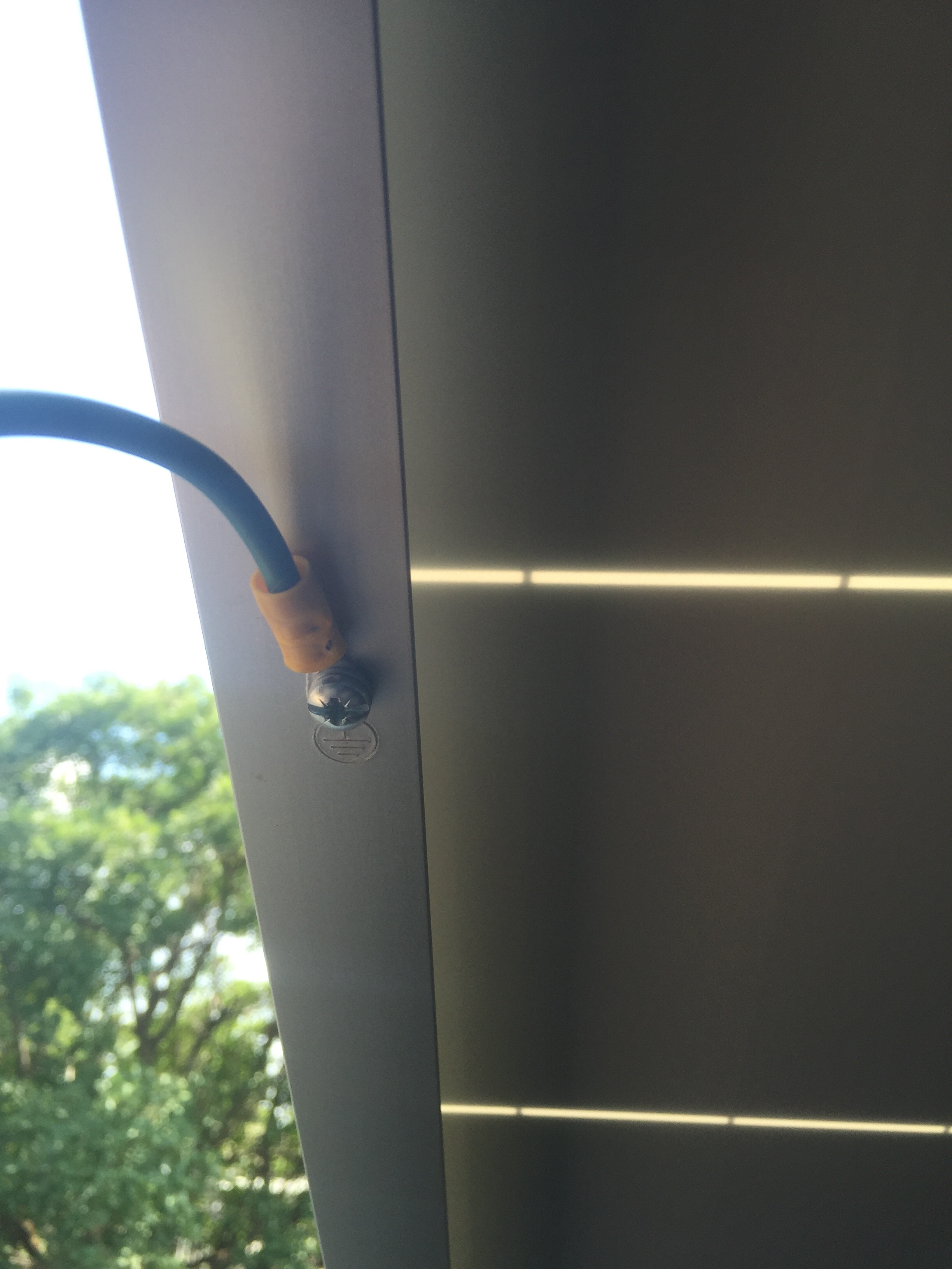
Over the weekend I've been able to put up the panels on the roof. It was a learning curve for me an I thought I'd put down my experiences (good and bad) here for others to learn from my mistakes and to find out if there are better ways of doing it. Firstly it was a bit more difficult than I thought it would be. Getting the panels to align up was was not so easy. I am sure that for people that do this for a living its a lot easier, but for me, doing it for the first time it took longer as I had to figure things out as a went along. I have 2 rows of panels. The top has 7 panels and the bottom row has 6 panels. The thing that made it difficult was the railings are not completely rigid, they tend to flex and sag slightly when holding the panels weight. Eventually I figured out that that fixing the bottom row of the panels first work for me. I then used the mid clamps as "spacers" to rest the top panel on them before fixing it to the rail. If I had to do it over I would have started with the middle panel of the bottom rail. Its critical to get it perfectly straight as all the others will take its alignment from it. The railings I have are galvanized steel and the panel frame's are aluminum. I've read on the forum about galvanic corrosion could occur between dissimilar metals. I've read that galvanic corrosion "might" happen between galvanized steal and aluminum but that its not a high risk combination. I think at the coast its more problematic. The way to prevent this is to isolate the two metal from each other. So what I did was to put some double sided tape (not the spongy mirror tape) between rail and the panel frame before tightening the mid clamps. The mid clamps are aluminum so no problem there. Its only where the panel touches the rail. I've read that some people used bitumen strips as well. The tape I use is called "nail it with tape" and is reportedly UV resistant and approved for outdoor use. It's quite sticky and was not easy to put in place. On the second day I decided to attach the earth wires to each one of the panels and railings. I used an insulated 4mm2 earth wire and crimped on some ring terminals. The terminals was attached with a spring washer and self tapping screw to the demarcated grounding attaching point of the panels. Cable ties were used to tie the earth cable to the panel frame and the railings to keep things neat and tidy. The panels are connected in one large string. Voc for the string is close on 500V. That could really spoil your day if you were to touch that!. The two end wires are fed back into the roof between two tiles. To prevent shaving of the wire against the tiles I cut two small pieces of gas pipe and fit it around the PV wire. It fits snug but not to tight. It was placed between the two tiles and holds the PV wire from touching/shaving against the roof tiles. I attached two PVC 4x4 junction box to the rafters closest to where the PV wires comes through the roof tiles. Inside it will be the MC4 connector that attaches the wire that leads to the combiner box. The wire going from the PVC 4x4 junction box to the combiner box is a 6mm2 Solar PV wire and will be placed in a 20mm PVC conduit. For now I've secured the two open ended MC4 connector into the two PVC 4x4 junction boxes to prevent them from touching anything. As soon as the combiner box arrives I will attach the wires to it (at night when the voltage on the wires are low. :-) My next step is to fix the inverter, grid tied limiter and combiner box in the "inverter room" wall. Then put in the trunking and do the wiring. Hopefully I get some time to work on it this weekend. Given what I've done with the panels so far, would there be something you would have done differently? One think I would have done differently is to try and attach the earth wires before or, as part of putting up the panels on the rails. Trying to access the back of the panels by moving tiles and working from inside the roof was not an easy or comfortable job! Some of the tiles can not be moved because the railings rest on them! That means you have to bend and work in very uncomfortable positions.

-
@jdp I'm going to switch over manually. It's a small generator that I will store in the garage, but will have to carry it out and plug it in before I can start it up. Its small and not that heavy.
-
@jdp I will only use the generator if an when we have a municipal power outage. @superdiy I agree with you. I'd rather not risk it. I'll switch off the GTI.
-
The typical generators produce a modified sine wave and as a AVR. When you switch on a heavy load you can hear the RPM changing (Hz also changes). So the power it produce is not very "clean". If I were to try and connect the GTI to it, it will most likely either disconnect because the power it sees on the "grid" does not fall within acceptable ranges (Volts, Hz and harmonics), or in the worst case it may blow smoke. That's why I am looking at an inverter generator. Thy work differently. It effectively has an inverter built in that produce 220V 50Hz sine wave. Its a lot cleaner than the typical generators (and more expensive). To prevent the GTI of pushing power back into the generator there is a Grid Tied Limiter. It monitors the direction of the Amps passing through it. If it detects that the Grid Tied Inverter is producing more power than the load is using it sends a message to it to reduce the amount of power it produces. It will try to balance things so that the Grid Tied inverter only ever procude as much power as is consumed by the load. The net power flow from the grid/generator will be 0 Watts. (This is all in theory). If the Load is consuming more power than the GTI can produce it will pull power from the grid/generator. Most likely I will err on the safe side and switch off the GTI if I have to run from the Generator. I really don't want to blow up the GTI or the generator. Most likely I'll only have to use the generator one or twice a year anyway.
-
Hi JDP. The grid tied inverter only works if it has a grid to attach to. So if the grid drops, the grid tied inverter will shutdown as well. I'll have no power in the house. I only have 2 sources that can act as a grid. The municipal power and the generator. I have a changeover switch which I can use to select which "grid" I want to use. In the rare event when out municipal power goes out (we do not get load shedding) I have to option to run the house solely from the generator (switch off the grid tied inverter), or I can run the generator and supplement it with the grid tied inverter. This is one of the drawbacks of the grid tied system. You need something to provide the "grid" for it to attach to.
-
Thanks Plonkster, I have thought of that as well. I do have a 6.5kVa petrol generator (modified sine wave - ugly wave form!) I am in the process of replacing because of that. I doubt that the GTI would appreciate all the harmonics that it produce, it may just blow out a lot of smoke if you try to do it. The plan in to get a inverter generator (pure sine wave). I hope it will work :-) I'll test it and let you know. One thing I am concerned about is feedback from the GTI to the generator. That is why I have the GTI Feedback Limiter in place. What I do not know is how accurately and quickly it blocks feedback. If it does allow some feedback momentarily the generator might have a problem. I can think of two ways around this. One, the GTI feedback limiter has some dip switches you can set to how much power it will allow to be drawn from the grid. You can set it to 0W or 50W or 100W. (In other words, if set to 100W the GTI limiter will try to force the GTI to produce 100W LESS than the load consumes, thereby allowing 100W to be sourced from the Eskom all the time. I really don't like to use this setting because if I set the dip switch I will always consume power from Eskom (50W or 100W) even if there is plenty of Sun/PV to power the full load. Two, I put two (redundancy) small incandesent bulbs/resistors in parallel between the Generator supply connection and the Grid Tie Limiter. In other words the incandescent bulbs should draw power BEFORE the Grid Tied Limiter. Since the Grid Tied limiter only measures the power (Amps) going through it, the amps going through the bulbs will be excluded from the calculation. When I run on Generator it should be enough to prevent feedback (I hope).
-
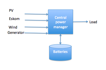
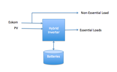
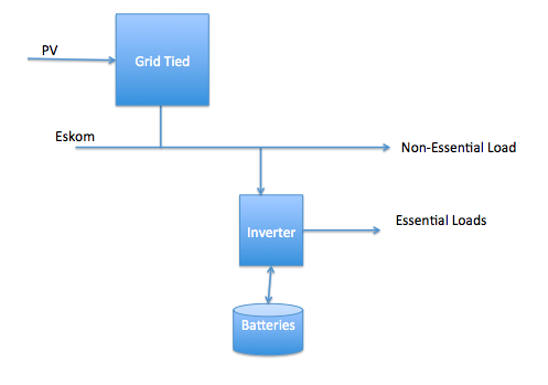
Yes, the plan is to only change the batteries during the day while the grid tied is producing power. But that is still some time away. For now I'll be happy with just the grid tied during the day. When I started investigating PV solar options I stumbled upon the MLT drives Powerstar system. What a nice piece of kit! but expensive! I just could not justify spending that amount of money on the system, but liked the idea that it could manage all the energy sources. Municipal feed, Generator, Solar, wind whatever and then manage the flow of energy from source to load. If money was not an option I would do something like that. The problem I had with it is that if you want to do this kind of thing with a "central power management system" that should be able to manage ALL the load (Lots of amps going trough it, large battery banks = lots of money.) Also if that one piece of equipment breaks the whole system is down. It also needs to be sized so that it can handle the entire load all the time. The other thing I looked at was to only do it for a subset of the load. The moment you want to power ALL the loads in the house the battery bank gets really large! So to keep the size of the batteries small enough one would only put the "Essential" loads on the inverter. Something like this: In this case the inverter is smaller (cheeper) the battery bank is also smaller (cheeper) but the PV you attach to it can only ever power the essential loads. If you have underfloor heating installed you would not want to attach that as a load to your inverter. That's why I like this option: The PV via the Grid Tied inverter can be used to power any and all load in the house (Swimming pool pump, geyser, underfloor heating etc). If its large enough and the sun shines you have power. The PV has a life expectancy of 25 years. ROI of that part of the system is quite good (over time it will pay itself off). The batteries on the other hand is the "expensive part" as you would have to replace them every so many years. The thing I like about this AC coupled system is that you can "choose" the size of of the essential load and thus the size of the inverter/battery bank. You also "choose" the size of the PV/Grid Tied side of the system. The smaller the inverter/battery bank side of the system is the better the overall ROI for the system. For now I will not have an inverter/battery bank, just the GTI and therefor optimal ROI. (Or so I'd like to belief ;-) )
-
Just bought the ACDC 63A one last week, was planning to install it this weekend :-(
-
At long last! It has started! I've been researching solar PV systems for more than a year now, reading as much as I could get my hands on. Some time ago I've stumbled onto the Power Forum and it has really been a source of inspiration and a wealth of information. Thanks guys! Let me give a bit of background as to what I have and what I want to do. Some years ago I bought an old house and started renovating and improving it. In the process I've tried to make it more efficient and less costly to run and maintain. I've been able to do the following: Replaced the old swimming pool pump with a Eco variable speed pump. The old one consumed 1600W, the new one uses 300W (Big monthly saving) Replaced old stove with a gas stove (unfortunately it has an electric oven) Replaced all Incandescent bulbs with LED down lights on a separate lighting circuit (Essential lighting circuit). Added additional electrical outlets (plugs) to all rooms. (Essential plugs circuit). Installed insulation into the roof. Installed underfloor heating in the kitchen (Before 2008 when electricity was still relatively cheep, do don't use it much anymore) The living room as an anthracite fireplace that keeps it nice and comfortable during winter, sometimes we also use gas heaters. Installed a 300L solar split pumped vacuum tube geyser. (That was when you could still get a rebate from Eskom - that helped!) We have more hot water than we can use. Only on the coldest,cloudiest winter days does it use some electricity to bring the temperature up to 55. What do I want to achieve with the solar PV system? My main aim is to reduce my monthly electricity bill in a "cost effective way". I don't want to change my life style. If I want to weld or grind I want to do it without worrying if the washing machine or other appliances are on or not. The system should require as little maintenance as possible. One of the first things I did was get an energy meter (Effergy) so I can monitor my consumption. (If you can not measure something you can not control it!) I was able to extract the data into a spreadsheet. With the help of Google, Nasa and other websites I was able to get a hold of formulas that I could use to calculate the solar radiation that would fall on my roof at a given latitude, angle (20 degrees east of north) and elevation (30 degrees) for any given date/time. I used this spreadsheet to estimate the how much energy I could produce (ignoring cloud cover) and subtracted that from the actual usage I got from the Effergy data. After all this I could estimate that a 3kw grid tied system would reduce my electricity consumption between 30% and 50%. I looked at the different ways to setup a PV system (Grid Tied, DC coupled, AC coupled, off-grid, etc.) In the end I decided to go for a AC coupled systems. I'll have a grid tied inverter that provide AC power to my house grid. Then have a inverter/charger that will draw AC from the house grid to charge the batteries. The inverter/changer will only feed the essential loads (LED lights, Fridge, TV, WiFi rooter etc). Since the inverter will only need to power the "essensial" loads it can be small and the battery bank can be small as well. The reason I liked this solution is that I could implement it in phases. Phase one I would implement the Grid Tied inverter to supply power while the sun shines. Any appliance would be able to use the electricity (poolpump, underfloor heating etc). If there are any shortfall between what the PV produce and what I consume it will be drawn from the Municipal connection. Phase two I will implement an inverter/charger and battery bank that only feeds the essential loads (the ones I use at night). Batteries are expensive and have limited life span. From what I could gather they are not really cost effective in terms of the cost per kWh they will store during their lifespan. This may change in future if the Rand strengthens, battery technology improves or Municipal electricity prices increase drastically. (Anything is possible) but for now I'll hold back on it. One thing I forgot to mention is that our area are not affected by Load Shedding for some reason. (I am not complaining). If we were affected by load shedding I might not have gone for a Grid Tied systems. One of the draw backs of a grid tied system that the inverter shuts down if there is no grid power. So if there is a power interruption 3+kW PV on the roof and the inverter will we doing nothing for me! We do get power outages (typically once a year or so and it can be for anything from an hour to a day or two). As a contingency I plan to make use of a small Petrol Inverter Generator (pure sine wave). Just a small one will do (3.5 kVA). At night is powerfull enough to power the essential loads and during the day it can boost the 3KW Grid tied inverter to produce up to 6.5 kVA. That should be more than sufficient given power spikes rarely goes over 5kW. Since last year I've been sourcing the various components and last weekend I started the installation. The railings that will hold the PV has been installed on the roof. The only component that I am still waiting for is the high voltage combiner box. As soon as that arrives I'll put the PV on the roof and do the wiring. Here is what the system will look like. If you have any comments/suggestion please let me know.