


Ronald W
Members
-
Joined
-
Last visited
Everything posted by Ronald W
-
Hi Guys Ok Goodwe has replied see attached. I'm not to sure on how true it is as the App aside. the battery indication on the battery itself always reflects that the unit is charge or discharging even when there is sufficient PV to drive the load anyone have constructive input to clear the air. or am I looking for a problem that is not a problem. if I look at the PV App then the only time the battery goes into Standby mode is when the battery reaches the set DOD. from what I understand Goodwe is saying that there App is not accurate. 😞 Not a good reflection on the product if they don't get it sorted. Thanks Thanks Guys

-
I would agree with your theory. But may be the BMS set limit too
-
I was thinking that it may be due to the firmware upgrade I had done. as I'm running 2121E that is newer than 2121A. It has only being doing it since the new firmware upgrade, this is the reason I have been thinking its a inverter issue and not battery. I do understand that the battery has to do a balancing cycle but surly this should not take days. also I have only had this issue with the new inverter.
-
My question is then why did the same battery with my old inverter Green ES not do it? (See attached photo) Cant see it being the battery when the only thing I changes was the inverter to the new white one. With my old inverter the 6 light uses to switch off when the battery was full and go in to standby mode. even the App used to indicate that the battery is in Standby mode. With the new inverter it only goes into standby mode when the battery hits the set DOD. when fully charged is cycles up and down.
-
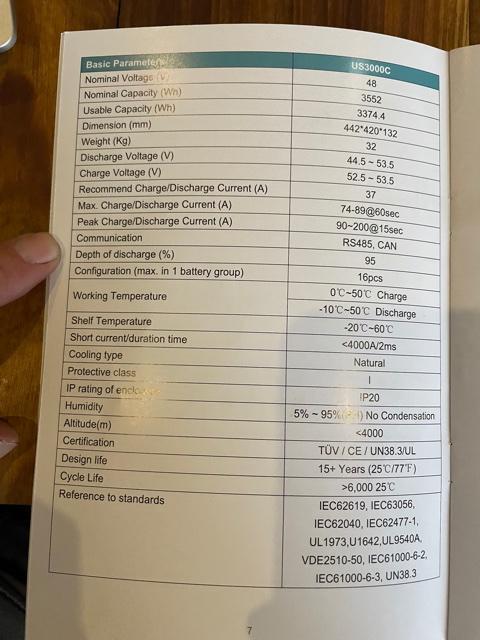
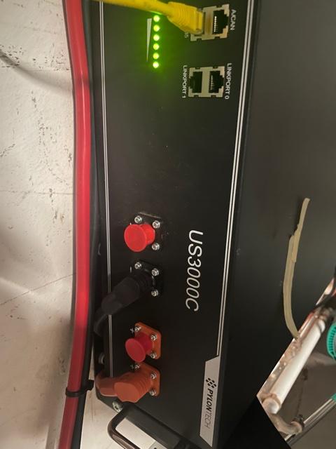
Morning Clf I have the same setup but only with one US3000C Battery. I can confirm that the max DOD is only adjustable to 90%. My unit has been update with the latest firmware. My firmware Version is 2121E. I would check with Goodwe if they can push the newer firmware to your unit if so required. secondly in my opinion I would not want my battery to drop below DOD 90-80%. my reason is it will prolong the life of the battery. more importantly is to ensure long battery life it would be best to ensure that the battery only does one cycle a day and not up and day during the day due to not having sufficient PV available on sunny days to drive the required load. STOP//// Before you upgrade firmware can you confirm what version of firmware you have??? The reason I ask is I think I have a bigger issue with my installation. what I have noticed is my battery no longer goes into stand by mode when it reaches 100% charge when there is sufficient PV available (Continuously Cycles the battery up and down between 99% and 100%) once its reaches 100% it then discharges at around 15 watts till 99% is achieved then charges up again. this I feel is damaging the battery. My installer has opened a ticket with Goodwe but we still have no feedback or solution to the problem. Can you confirm if your unit does this? (I have attached some screen shots understand that all screen shots where that at mid-day when the sun has been blazing. (More then sufficient PV Available) My concern is that the battery never goes in to standby mode when not required. lastly May I mention that this is my second ES inverter as I upgraded from my 2016 model to a new serial number 9------ onwards. The issue mentioned I never had with my old inverter Serial number 3------- onwards with the same battery may I add. so for this reason this cant be a battery issue. Let me know what your inverter is doing in this regard.


-
Well the salesman lost out on the sale and I spend more money then I should of 😞 if that is the case. But be that is it is Im happy with my current system.
-
You will really need to check that as I had the sales man from Ellies electronic confirm that it does not feed PV to the non-essential side. As the Sunsynk is a grid tied inverter it would be mandatory for it to have a CT coil to comply with many country's (Municipality) regulations on PV installations. secondly the inverter would require the CT coil so it can know what is happening with the grid. The inverter requires the coil to adjust the frequencies (HZ) so it can achieve the zero feed back setting on the inverter. lastly I'm sure the inverter would also require CT coil to correct the frequencies to the grid when selling power back to the grid. If the Sunsynk inverter could supply power to both sides then its worth the money that you pay for the unit and I would have one on my wall and saved myself about 8K on my current inverter. Im sure there must be someone here that has the inverter installed and confirm this is true or not. If @Gerrie is correct and the then Sunsynk push the power to the Non-essential side FROM THE PV PANELS and not the grid then inverter is a good option.
-
Hi All @Nicholas Baard I hope you don't mind me giving my opinion on this discussion? I have a Goodwe ES4.6 and currently very happy with it performance. All inverter have their pros and cons so one would have to select the inverter depending on what you what to achieve taking into account what your wallet can afford. The reason I selected the unit I have is that it is one of the few inverter that the PV will supply Grid side when there is sufficient PV Power available. this function as far as I am concerned is advantages when it comes to saving on the electrical account there by reducing the payback period of the system. Or alternatively one can just get a bigger inverter that can drive all the loads but with this comes at a higher price as not only do you need a larger inverter but you will need more panels and battery to suit as you would be driving all the loads simultaneously . I have a small setup currently (6x 455kw Canadian Solar Panels, one Pylontec US3000C battery and a Goodwe ES4.6 inverter) and I have already cut my electric bill by at least 75% and have had sufficient battery power for load shedding. My plan is to improve the system by adding battery's and PV Power till i don't need the grid at all. This weekend I will be adding additional 1820 watts to the roof and will continue adding requirement till I have achieved the max my inverter can handle. Initial I was really sold on the Deye/Sunsynk unit but was told that it can only supply PV power to The essential side of the inverter. I have still split my DB board with the essentials and heavy side but to me it made no sense when the cost saving in power is mostly on the Grid side of the inverter. If you looking for an inverter for a Back up system for when there is no grid available then the Deye/Sunsynk would work just fine. It would be interesting if the guys in the know could comment on what inverters are available that have the ability to supply the excess PV power to the grid side of the inverter (Heavy Loads) hope that helps
-
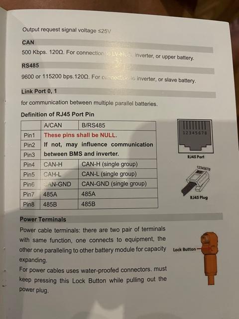
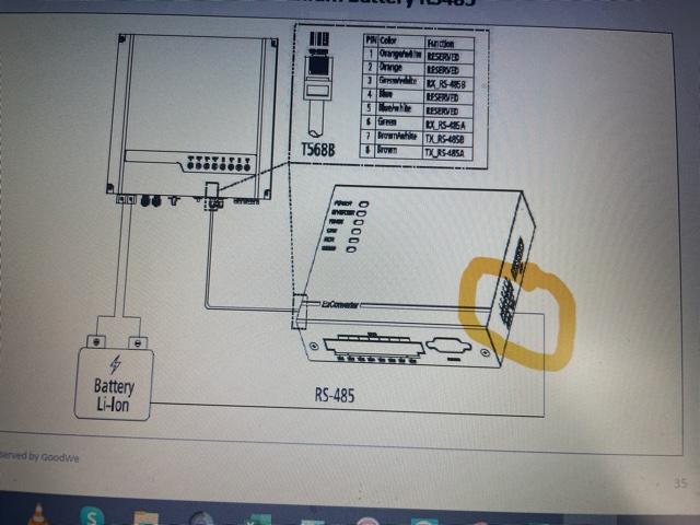
@Neil@dropkick @87 Dream OK now that the system is up and running and Neil was so kind to help out and point me in the right direction I have notice something I need some comments on. Looking at my battery booklet i now see where the termination point are and they are slightly different to the info @Neilwas so kind to share. I have now noticed that my battery model I have requires the GND to be terminated to PIN 6 on the RS485 connection on my US3000C battery. Not sure why it is functioning with GND terminated to pin 2 . SHOULD I CHANGE THE CONNECTION TO pin 6, EVEN THOUGH THE SYSTEM IS FUNCTIONING WELL. (See attached photo from my battery Manuel
-
Hi All A big thanks all up and running. @87 Dream @dropkick @Neilonly one question, now that I have the BMS communicating i have set the battery setting to Pylon US2000B * on the App as that is the only Pylon battery available under the battery selection on the APP. now that i have done that I see that charge current and the discharge current has been Limited. The discharge current to 25.0 A and the Charge current to 24.8A. (However this is setting is now greyed out and I cant changes this. Is it not best for me to change back to self defined settings. this way I can change the charge and discharge rate to the manual. what you guy recommend???? See attached screen shots and Photos. Thanks again to @87 Dream @dropkick @Neil for all the help. FYI Way sooner that waiting for GOODWE SA to help.


-
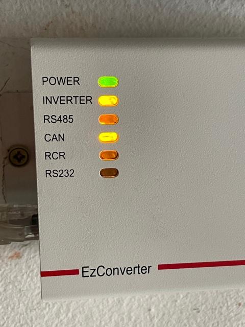
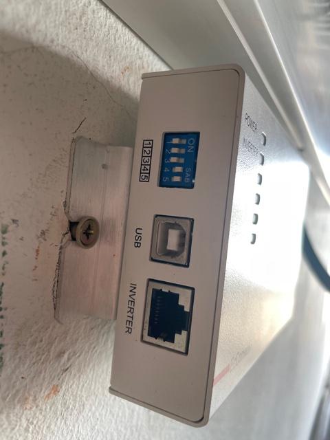
Here with Images requested. I have the unit up and running on self defined setting given to me By the goodwe sales rep. I just hope they correct as they could not solve my EZ Meter issue. I have to open ticket with GOODWE myself and eventually get the issue sorted as mentioned before. I will rather wait to have the correct info on hand before I connect the EZ converter as they not easy to come by. I would hate to blow it on an incorrect installation. Mine I had to have shipped to me from Germany as Goodwe have non for Sale and chine say they no longer in production. Thanks


-
What I have noticed is that my battery only Has 4 dip switches see attached Photo

-
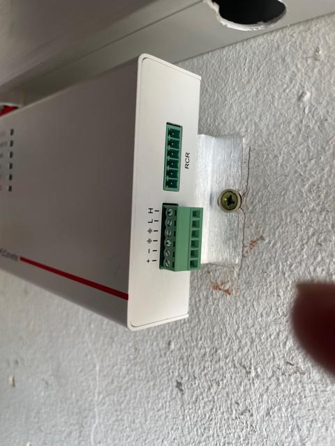
Hi Drop Kick Thanks for your willing to help me with the issue at hand. please bear with me on this as most of your comments are above my Pay grade. The situation is as follows: I have an older Goodwe ES inverter serial No: 3-------- that i have installed. I have it running on a Pylon US3000C Battery. Currently on self defined settings. I want to get the Battery BMS to communicate with the inverter. for this reason I have managed to get the needed EZ converter that the manual shows is required to get this done. The manual is however not clear on the wiring termination required between the Battery and the EZ converter termination Block. (See Attached Photo) From what I understand on the Dip switches and the document supply in your above comments is that the Pylontec battery is to be set as follows: Battery DIP Switches as follows Switch1: OFF, Switch2: Off Switch3: On Switch4: On, Switch5: On What I have read on this forum is that the EZ Converter DIP switches as to be as follows: DIP switchs 1,2&3 are to be OFF and 4 and 5 are to be on see attached photo. The only unknown is where to terminate the wiring on the EZ Converter. For now I haven't wired it up yet as it is not clear on where to fit the wiring and DIP switch layout. Im also not to clear if the plug must go in the CAN port or the RS485 Plug on the Batery. Off the topic I must mention that when connecting the EZ Meter to the inverter I had some difficulty getting the correct info out of the GOODWE online help service. But after +/-2 weeks and many frustrating discussions It was found that one had to pair Green & Brown pin 2 and white/green to be paired with white/brown Pin 1, On Discussion with GOODWE SA they admitted that due to the Age of the inverter that no one that had the understanding on how to sort my issue out. A very frustrating ordeal. This is the reason I have now tried the forum to get this solved. Thanks again


-
Morning @87 Dream @dropkick Ok I have read the info recommended but the question still remains. The cable from the CAN port on the battery to the EZ Converter. I still cant see or understand what pin number (Color) on the RS485 plug and the point to terminate it on the EZ Converter. The manual only reflect an illustration for the cable between the EZ Converter and Inverter. nothing indicating the connection layout on the EZ converter coming from the CAN port on the Battery. Se attached photo


-
Im Based in Port Elizabeth South Africa
-
Hi Yup I have a convert that I managed to track down. The connection between the Battery RS485 to the EZ Converter is what have a issue with. The manual does not what color wire to terminate to what points on the junction block of the EZ converter. secondly I would need to know how the dip switches need to be configerd on the Battery and the EZ Converter, I have attached some photos.


-
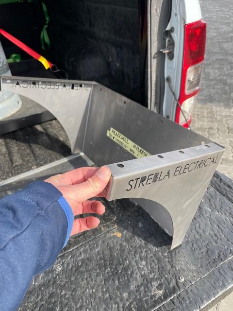
MMMMM!!!!!! This was designed by me, built by me, for me 🙂 Never thought of marketing it either. Looked around and could not fine one to purchase in the design needed to suit my requirements. the only down fall to it if stacking more than two batteries one will have to ensure the cable lengths between batteries have the same length. secondly you will also then require longer communication cables. Just my thoughts on the matter. maybe there is someone on the forum that is more qualified to comment. You can PM me if you want the DWG Drawings. then any steel merchant can bend it up. 4 small welds and powder coated in the color of your choice. Good to go.
-
Hi Peet 1: I manage to locate a EZ Converter on Ebay and have it shipped to me from Germany, Try That. Q3: I had the same problem when using My Iphone, for some reason. so with my I Phone i use the EZ Manager App. The PV Master app does seem to work with the Android app, the Above is on the older ES inverters with a serial break 3--- Hope this helps
-
Hi Chaps Thought I would share my battery mounting bracket. One can mount 2x Pylontec US3000C Thanks

-
Hi Hoping someone can help with a wiring diagram to install the EZ Converter that i managed to find at last. I have the older ES Goodwe inverter starting with serial number break 3-----. Batteries is a single Pylontec US3000C. The Manual is not to clear on the pin allocation to connect the RS 485 Cables from the converter to the batteries. further more I will need to know the Dip switch setup on the Battery and the EZ Converter to get the BMS to function incorrectly. Any further input would be appreciated. Thanks RonaldW
-
Ok it looks like the unit I have. Same serial break. I’m looking to also fit batteries with a BMS system. Let me know how you solve this one. looking to fit Pylon tech 3000 batteries. also can’t find a EZ converter to integrate the BMS to the inverter. looks like we will have to set up on user define settings.


