BigC
Members
-
Joined
-
Last visited
Everything posted by BigC
-
@Powerforum Store.. thanks for knowledgeable response. And @frivan for your simple suggestion. Since the generator is a manual start, there is no hardship in operating a bypass switch from grid to generator, so I will implement that this week. The budget is a concern, so the suggestion to live with the Solis on the gen port and add the CT makes sense and is easy to do, since most of the work has been done already. If the weather permits enough sun this week I should have my answer soon.
-
Then you lose the contribution of the 3rd string during load shedding, which is kinda when you need it most. It's a tossup .. it's the cheaper solution, but not elegant at all.
-
Hi everyone .. it has been a while! I successfully got the Solis to work on the Gen port, using the frequency shift feature of the two to shut down the Solis when the batteries approached 100% SOC. It was not without problems since the Deye would occasionally "leak" power back to the grid because the Solis was too slow to respond and the grid smart meter would disconnect the grid. However, a bigger problem, after a lengthly grid outage (many days) in the Overberg, was how to add a standby generator to the system? Connecting the generator to the Deye grid port worked, but not a long term option. What I am going to try next is to connect an el-cheapo/used hybrid inverter (like a Kodak) to the Gen port and the generator to the Kodak grid port. Theoretically this should work well, with hopefully no over-feed problems. Question is .. can the Kodak work battery-less in this work-mode. If not a Kodak, does anyone have experience or suggestions on what inverter would work here? I so look forward to your responses .. love this stuff 😄
-
Thanks for your comments. The Deye does make this distinction with a tick box. Earlier today the Deye FW was updated, so I am hoping to see a change tomorrow. Additionally I will be assisted tomorrow by Solis to verify it's settings as well . . . 😀
-
Illness, weather, installation of 9 x 460W panels, and the addition of another Blade battery have delayed the commissioning of the system somewhat. However, it is all working well .. I got rather excited .. up to the point of the batteries reaching 100% SOC. Sadly the inverter does not react to this situation by increasing the frequency on the Gen port. Hence, at some point the inverter turns off the supply to the Solis with alarms sounding and all manner of consternation. The faults logged by the Solis are consistently "disconnected from the grid" It would seem that this Deye has older FW .. Ver 0-5388-1516, which does not implement this means of regulating the Gen port output. Additionally, I have no experience of the Solis inverter and the configuration seems a nightmare. I therefore have no idea whether its present configuration is suitable. First off I suppose I can lean on Deye support to download the latest FW .. is this a no risk scenario?
-
@HennieL : The garage roof is fully utilised and additionally not optimised for angle, etc. Additionally, the cables and panels were installed in clusters (don't understand why). The new panels will go on the house roof. I would have preferred to mount the Solis in the house and run a mains cable to the garage, but the configuration suggested below works much better .. will have to run PV cable to the garage instead . . . Thankyou @Scorp007 and @GreenFields .. "If this is all correct, then the logical thing for me would be to connect the single string off from the second Deye MPPT, and connect it back to your Solis 4G again (this time with the Solis inverter connected via the AUX input). This will free up the MPPT on the Deye that can take a 5200W string at least". That is the conclusion I came to. I spent some time on ChatGPT exploring all this. The result is 4.1kW (9 panels at 460W) + 2.6kW on the Deye and 2.9kW on the Solis giving me 9.6kW total. This is close to the 190A max charging current. I think this is as good as it gets. ChatGPT suggests keeping the Gen port input substantially lower than the onboard MPPT input as, it seems, the Solis responds more slowly to the frequency shift generated by the Deye and this can cause hunting. Thankyou all for your wonderful and knowledgeable contribution to this thread. I have confidence now that this will work .. can't wait to implement this upgrade. Ciao . . .
-
I love this solution .. now to commence the install. Thank you all for your valuable contribution to my enquiry. All done and dusted in < 12 hours. I just enjoy this forum . . . 🙂 PS . . . I may need help with the configuration, but will cross that bridge when I get there. Ciao . . .
-
@GreenFields . . . Just to clarify, the existing panels are old and were installed on 3 different occasions, as 3 strings, on a roof that is impossible for me to access. The cables all ended up in the garage, where I was able to measure OC voltage and SC current, and then carefully connected the panel sets that were identical in current, at least, into 2 strings. It is not possible to identify them, or change the configuration. @frivan and @hoohloc have identified a possible solution. I have 3 x Solis mini 2500 inverters (removed from the old installation)! However, I don't see how they can connect to the Aux/Gen port. Surely the grid-tie inverter needs to see a grid? Would the Gen port work like that?
-
If I opt to fit a second inverter rather, say a 3.6k or 5k unit, which is a bit more expensive, then you lose nothing .. just as long as they are compatible when connected in parallel. Can one mix inverters, as long as they are from the same stable?
-
2 dissimilar strings totaling 27 mixed panels, cobbled to give me 2 nice strings of about 4500W total. They were inherited so I did the best I could. They are working well. As @Kalahari Meerkat suggested, I may have to forgo the BMS connection, configure the battery mode as "use battery v" which means I lose some of the battery metrics. Was hoping someone tried this before I spend the bucks . . . 😆
-
I have a problem. I have 4k5W of panels in 2 strings feeding an 8kVA Deye inverter and 7.2kWh of Blade battery. I wish to add a further 4kW of panels (and another battery), but do not really require a bigger inverter. the solution is to add a Victron 250/60, say, charger to handle the extra string. Can this work, or will the Deye MPPT throw up it's arms in despair? Is there another solution that the esteemed members of the forum may have up their sleevies?
-
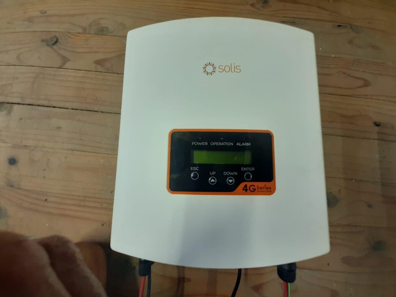
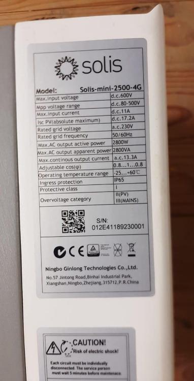
Item: 2 off Solis mini-2500-4G Solis S6-GR1P2.5K Solis EPM3-2G Export Power Manager Age: Bought early 2023 before load shedding really kicked in, and subsequently found to be unsuitable since only grid-tie. 3ph supply converted to 1ph and inverters being upgraded to a single large hybrid inverter, with the intention to move off-grid completely. Price: Solis minis .. R4500 ea. Solis S6 .. R5500 Solis EPM3-2G .. R 2500 Payment Method Accepted: EFT Warranty: Expired, but sold as working units. Packaging: Condition: Excellent Location: Stanford, Overstrand Reason: Upgraded to 1ph hybrid Shipping: Courier Collection: Link:
.thumb.jpeg.65a2c42d9b86c6c2bba9167abe39feda.jpeg)
.thumb.jpeg.660908df1c579856f0d91a6a7476a3f4.jpeg)
.thumb.jpeg.721a3cc322981484d4e090a3df9b2091.jpeg)
.thumb.jpeg.310aed04670a25eb360cfd9eac134f0f.jpeg)
.thumb.jpeg.89c7c6c6c41f9e2f5ee25d4e98a7397b.jpeg)

-
No .. just twisted pair. Seems that I should have used a shielded cable, or maybe even cat5 with the 4 pairs all in parallel (sort of) which would have been a better 'twisted pair'. Given the effort of burying the cable (in conduit) and pulling in more expensive cable, I am hoping the client will live with problem.
-
Hi @Sc00bs .. Apologies for the long delay .. The client went for the 45m of cat5 cable, so sorry .. no feedback. However, what did happen is that the 40m extension for the CT for the Deye inverter has proven to be problematical. Readings of load power on the inverter and on Solar Assistant are negative by a small amount .. once loaded the readings look normal. To test the connection I did the following: Removed the CT from the incoming grid cable .. problem remains Disconnected one leg of the CT at the inverter .. problem remains Reversed the polarity of the CT .. problem remains, although readings of load power are now negative. Disconnected both legs .. problem solved Despite this problem the inverter continues to export power back to the CT normally. I expect there is some low level interference in the long CT circuit.
-
Thanks @Sc00bs Looks like the answer to a maidens prayer. I will report back once I've tried this . . . Ciao
-
Hi .. I have a Deye inverter 50m away from the main dwelling and wish to connect via a Solar Assistant Pie. The range is way too far for ordinary WiFi, too costly for a long range WiFi system, and a cable is just way too difficult to implement. Question .. Is the data from the serial port slow enough to consider some other form of low cost wireless link such that the pie can be placed in the main dwelling near to the fibre router?
-
Hi .. The 3 sockets are all wired in parallel, so it is hard to imagine only one being faulty .. I expect the socket internals are faulty. The connections are easily accessible once the cover is removed. If the inverter is new, then you have a legitimate warranty claim. I don't understand "top plug" .. all 3 sockets are mounted on the top of the machine in a row towards the back of the inverter. Hope this helps. Ciao
-
I am hoping that someone knowledgeable of the rules, or has experience here, can help me find a solution to this problem. My client has a cottage separated from the main house by about 30m. There is an existing 2.5mm² T&E cable supplying power to the cottage. There is no electric geyser or stove, only lights microwave, kettle etc. However the cottage is perfectly suited for a 2k3W PV array, and the client wished to mount a 5kW Deye and 5kWh battery there as well, as they are out of the way from the rather small main house. The solution which suggests itself is to run a 6mm² 3 core armored cable to provide power back to the main house .. this would be the load circuit of the inverter, and most likely the entire power for the cottage. The 2.5mm² T&E would only be required to power the inverter. Needless to say the charging power from the grid would be severely curtailed. Where I need guidance is in the earthing and grounding arrangements for the panels, armor sheath, earth core of the cable, etc. What makes sense to me is to earth the panels to the armor sheath and connect to the ground spike (at the cottage, if it exists). At the main house the cable sheath would also be connected to ground spike, which also provides the earth for the N conductor and earth for the house in general. The earth core of the armored cable would necessarily also be connected in the DB to this same earth. I would provide for surge suppression at both ends of the cable, to prevent any differential voltages due to the long earth connections. I hope this is clear enough .. I have a sketch but that may well provide too much info and confuse the issue.
-
Hi Coulomb .. you are exactly right. I did just that and the fan does run flat out from a small 12V dc adapter. I discovered that the 3rd yellow wire is a form of speed indicator/sensor from the fan motor. Without that the inverter beeps and goes into fault mode. That impresses me as it means the functioning of the fan is monitored by the inverter as a crucial item. It is all working nicely. The one condition I could not test is .. what happens when the inverter shuts off the fan and the sense wire continues to send a voltage, which seems to be proportional to fan speed. Hopefully nothing, in which case the system should continue to work beautifully. Since you need access to that, you actually need to cut the fan wire and connect in a small piece of vero-board with the 2 diodes ORed. I also reversed the fan as I have mounted the inverter vertically and it makes more sense to draw air in at the bottom and exhaust at the top. With all my experimenting and powering up and down continually, my regard for this little cheap inverter has increased many dBs. I have noticed that the 12V dc stored on the caps does not bleed off, so I now connect the battery to the inverter terminal via a 10 Ohm resistor briefly to avoid that disturbing "snick" when connecting the battery. . . . chuckle!
-
Hi .. I have recently acquired a Mecer 1200 (12V) and a Hubble 120 lithium battery. I was very mindful of the sudden demise of these inverters after some time when connected to lithium batteries, so monitored my system very closely. Lo and behold .. from time to time the fan would turn off when the battery voltage rose to around 13,5V .. after which the case would start to warm up. I therefore surmise that this is the precursor to the smoke coming out! I can't imagine the reason for this but it would seem that some internal software mechanism assumes the battery to be charged and shuts off the fan .. not necessarily repeatable either which would explain why it seems to happen randomly. As a temporary fix I attached a computer type fan on the outside of the inverter (holes line up perfectly) and connected the fan to the battery terminals .. which is more a mechanical problem than electrical). The two fans now work in series. It works a treat but the fan can never be turned off. It has a power drain of 2W so not a big problem. However, I would much rather keep the internal fan powered up while the mains is connected (this would cover the case whilst charging). Does anyone have experience of doing just that. I am prepared to waive the warranty to achieve that .. much more satisfactory than trying to return the unit for a repair, which would cost in the end.
-
I'm not using the gen port at all .. how do you untick it .. by double tapping it? Only charging is via the grid connection. I set nothing up for the battery since I left that up to the BMS. Seem to remember seeing 40A discharge, but 100A charge, which doesn't seem right. However, the inverter max charge setting is 50A I seem to remember. LS kicks in at 2200 so I will get the owner to try that.
-
Hi forum .. I am rather at my wit's end with this problem and I'm hoping someone may have experienced similar or has a clue about what is going on. The retail supplier does not answer emails or respond to phone calls and China seem unable to help, probably because I don't have solarman running (no internet at site as yet). In a nutshell .. the inverter is paired with a Dyness 5k battery, with a CAN cable connected correctly (battery BMS reveals what looks like the correct parameters). The system is setup as a UPS with minimal parameter changes from the defaults. After 2 weeks the inverter started flagging the F56 error at the start of load-shedding, sounding the alarm, and shutting down . . . this would repeat every few minutes. The only load on the inverter was basically LED lights. Killing the load, by bypassing the inverter, stops alarm. The monitor screen showed a text message in red .. 'Smart' next to the 'load' icon. All the while the battery stoically reveals no problems .. voltage is steady at 53.14, SOC is close to full. What emerged after studying the various screens, was that somehow the GEN PORT USE had the 'smart output' ticked with 0W set in the power window. This was corrected .. 'generator input' ticked. The 'smart' message disappeared but the error recurred. As a hunch I upped the 'smart output' power setting to 1300W and all was well, until a 1800W toaster was turned on. Why should that be when 'smart mode' is not selected? I am beginning to suspect either a finger-poken problem, or a mains borne glitch that corrupted some parameter somewhere in the machine's little brain. I tried a 30 min total shutdown and reboot, but alas, that did not fix the problem. Next trick is to try a factory reset, but I am apprehensive re the default settings, etc. Any clues anyone, or information, or suggestions please. Ciao
-
I have no experience of the Victron inverters but did see a diagram that suggested that one of the variants seemed to be both an on-grid and off-grid type, which would place it in the Deye/Sunsynk type. This comment applies to the Goodwe as well, and I am sure there are others. It would be useful to get some feedback from other more knowledgeable members .. there is so much to learn here.
-
Oh noooo .. there is an error in the first diagram. It should read "Voltronic type inverters" .. sorry 😬
-
So-called hybrid, and/or off/on-grid inverters have evolved into a plethora of types that is quite bewildering .. and there are definite followers of the various brands, I guess driven by their experience and familiarity with them. Even the word hybrid has come to mean different things to different people. In an attempt to understand their inner workings I produced a few diagrams to describe these inner workings, based on studying the specifications and to a greater part, the experience of the many contributors to the forum. As my understanding grew, the diagrams reduced to only two .. the Voltronic type, which is a pure off-grid inverter, and the Deye type, which is both off-grid and on-grid. The two types being differentiated by their firmware functions and the sophistication of the hardware blocks. Despite no mention in the documentation, the Deye seems to have a bypass function same-size the Growatt (had some experience with both of these inverters). I witnessed this by measuring the Deye inverter output before and after the grid input was killed. No doubt the inverter outputs the higher 245V here in the Overstrand rather than the programmed 230V, when On-grid. AFAIK, this bypass is permanent. In the event that the grid fails, the grid is disconnected and the AC/DC output inverter block (which is permanently connected, powers the output. There is a Victron diagram which shows this very well. I'm pretty sure they all feature an internal DC bus at a high voltage (as in the Growatt) that is required by the AC/DC inverter block to manufacture the 300Vpk voltage of the sinewave output. The bus is powered by: 1. the DC/DC MPPT converter(s) 2. the DC/DC bi-directional battery converter 3. the bi-directional AC/DC grid inverter. I guess the ability to blend power from the various blocks, is predominantly enabled by the firmware, not the hardware, as I imagined. This final stage is the bi-directional inverter .. the magic all happens within this block. This stage drives the AC load output, but when programmed appropriately, can drive the grid connection as well. The CT connected to the grid input is what enables the inverter to power devices on the grid (or non-essential load) side, without pushing back onto the grid itself. The Aux port is merely a switched configuration of this inverter block. Methinks that output inverter block, and the sophisticated firmware required to drive all the electronics is what you pay the big bucks for. I write this in an attempt to promote a clearer understanding of the different inverters, and sincerely look forward to feedback, criticism, correction, or whatever, to this article. No doubt there are many vastly more experienced and knowledgeable folks out there who may have different opinions, or information to add.


.jpeg.ce5d58695152727563224664bb7667fb.jpeg)
.jpeg.90b26e3f84967ae845549903bd8dbb10.jpeg)
.jpeg.3787ad21bef0858659d8717d84f3dc08.jpeg)

.jpeg.972774676267e5adc12f11fc3dda25bb.jpeg)
.jpeg.3ae986d5320bea4f527e985cf699bb39.jpeg)