Marcodp
Members
-
Joined
-
Last visited
Everything posted by Marcodp
-
@Steve87 and @Virwat, for clarity and learning, could you elaborate on the Neutral/Earth bond relay ...what it is/looks like and how one would connect this? (Pictures would also help) ?
-
Thanks @Antonio de Sa - that would be an option although I already have the 10mm cable 🙂 - just need the time to actually do the work 🙂 Your sharp eye caught me out before I got the chance 🙂
-
@Antonio de Sa, you have a good eye - it is 6mm which is incorrect ....it must be changed to 10mm. The original install was a 5kva and was later upgraded to 8kva but the wire was not upgraded at the time so must be re-done which is such a huge irritation 😞 - in the interim the 6mm cable is being protected by a 32A MCB. Without a doubt, the Deye/Sunsynk 8kva requires 10mm Cable as the inverter spec has a max AC output current of 38.3Aa.c with a continuous passthrough of 50Aa.c.
-
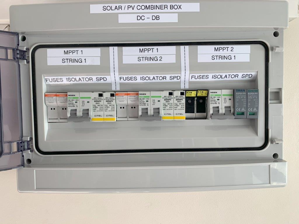
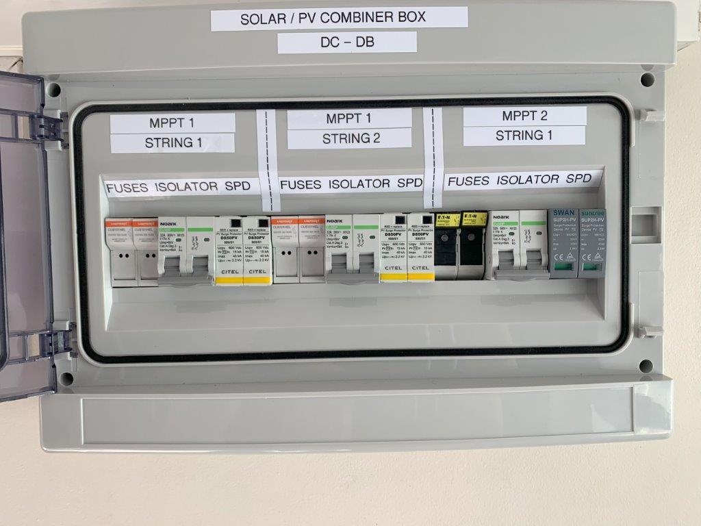
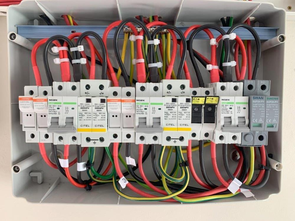
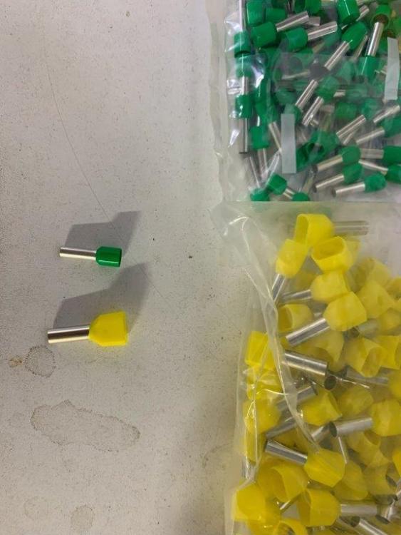
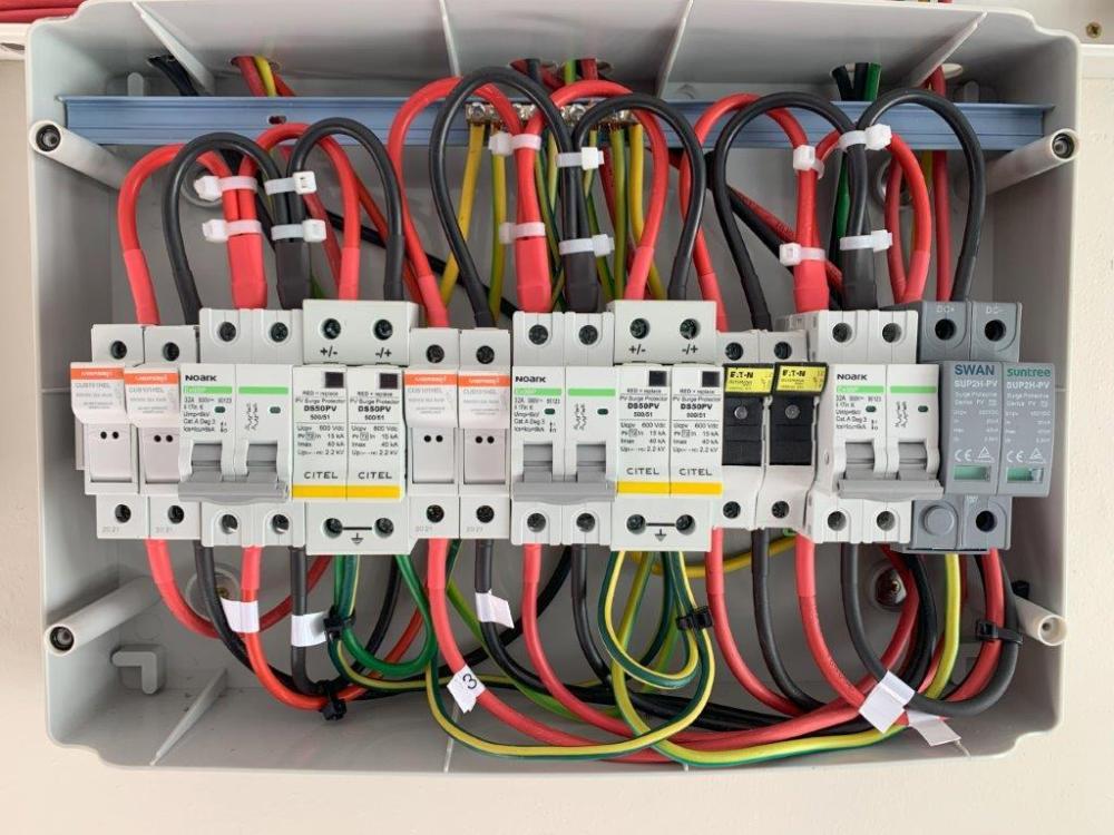
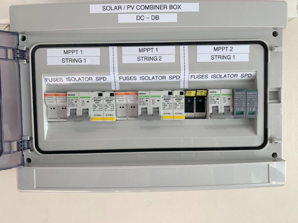
I recently managed to obtain a Solar CoC for "my" solar installation which consists of 8kw Deye Inverter, 24 x Canadian panels (10360w) and 2 x Dyness 5.2kwh batteries and have attached the pictures of my Combiner Box as reference. In this installation, as can be seen in the picture of my combiner box, I have 3 strings. 2 of the strings are paralleled at the inverter (MPPT1) and 1 string is on its own (MPPT2). Each of the strings have their own fuses (x2), a No-Ark MCB (and SPD). For my installation, each wire from the solar panels (positive & negative) goes through their own separate fuse (entry at bottom of fuse), which then go to an MCB (isolator) and doubles to an SPD. From the bottom of the MCB, the wires go to the inverter with 2 strings going to MPPT1 (paralleled at the inverter) and the 3rd string going to MPPT2. An interesting point (relating to combiner boxes) that has come to light, through the process of my recently obtaining a Solar CoC (Dec 2023), is that within the Combiner Box, you need to fit Bootlace Ferrules at the end of each Solar wire (stranded wire). This is required for both single wires (single wire bootlace ferrule) and where 2 wires are going into a MCB (twin wire bootlace ferrule). A CoC discussion can be found here:


-
In my humble opinion, a combiner box is a must and although opinions do differ, I prefer not to skimp and to have each wire (positive & negative) going through a fuse (correctly sized for your panels) then going to a 2-pole Isolator (correctly sized) and the use of an SPD (Surge Protection). Remember to use Bootlace ferrules in your combiner box for all solar wire (stranded wire) Herewith an interesting discussion about how to size a combiner box: as well as what you need to get a Solar CoC (Certificate of Compliance): Hope these threads will help?


-
My 2-cents worth, the Inverter notes a couple of things: 4000w x 2 Max VoC - 500v MPPT Voltage: 90-450v To me this refers to 2 x MPPT each able to take 4000w, with a max voltage of 500v Looking at the picture provided of the Solar Panel spec, it refers 545w panels with a VoC of 49.68v You have to look at Wattage as well as Voltage (although Voltage is the most important measure) - assuming that the panel VoC is at 0 degrees (Voltage increases as temperature drops, so you need to check the Panel specs carefully along with where you live and the min/max temperatures), if you take the Inverter max VoC of 500v and divide by the panel VoC voltage, you can add 10 panels per MPPT however each MPPT can only take 4000w, so 8 panels would probably be the limit (this would then calculate 397.44v / 4360w). The wattage is above the 4000w stated on the inverter, but it is highly unlikely that you would get close to the 545w from each panel. If you are unsure and really want to play it safe, try 7 panels per MPPT. Looking at the Inverter spec, it looks like max DC input is 16A, which does not allow you enough to parallel strings which is a pity. Herewith an interesting discussion around a similar topic:
-
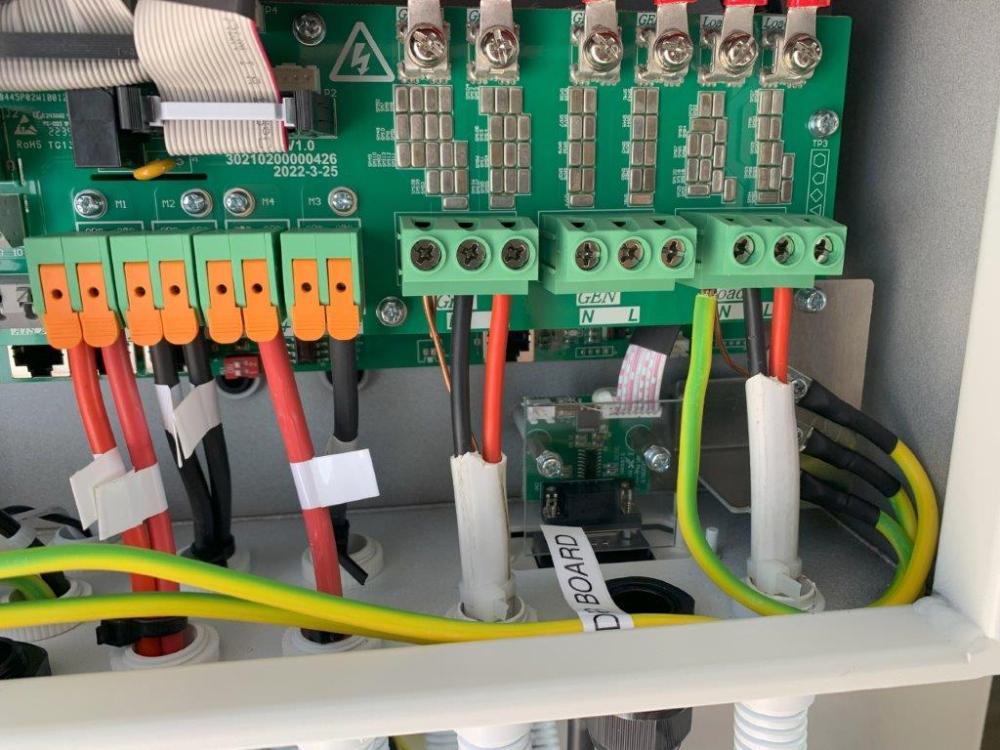
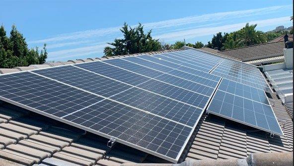
For an update, I have now completed the installation of my additional panels and thought it best to provide an update and provide some pictures/insights - I have also obtained a CoC for the installation - thanks to everyone for the input received above as this made it all possible 🙂 (with the CoC being the cherry on top 🙂 ) My Installation now consists of 8kw Deye inverter, 24 x Canadian Panels (10360w) and 2 x Dyness 5200 batteries - pictures of final installation below I am very chuffed with the installation so a BIG thank you to all !



-
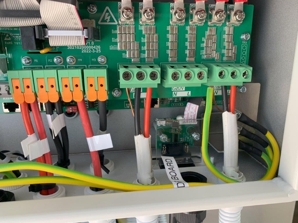
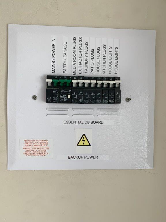
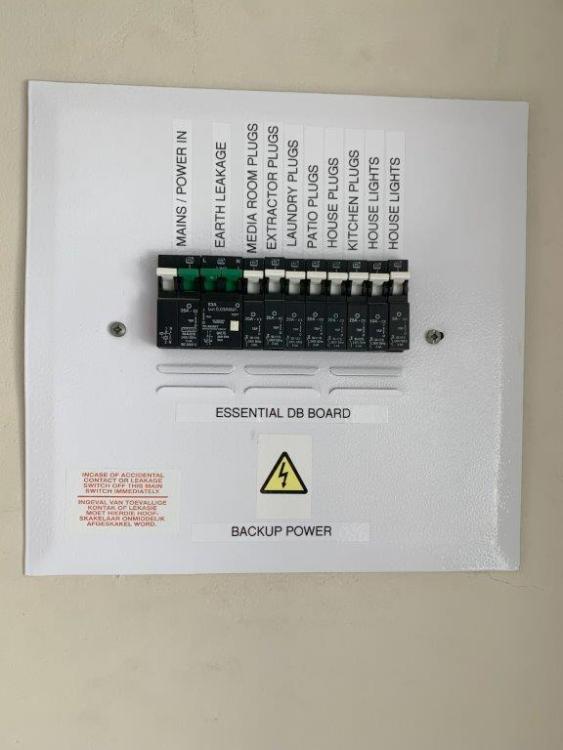
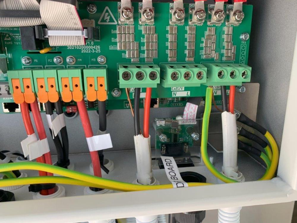
Thank you to everyone for good feedback and comments received. Disclaimer - the below feedback/item list was received for my installation, and is how I was assessed during December 2023 (It is recommended that one always check with the authorised/approved assessor for what applies to your installation) So, as mentioned, I have been assessed and have received my Solar CoC - I thought it would be good to share some of the items that were checked by the assessor (there may have been others, but these are the ones I asked about and made notes on) Firstly, during the discussion with the Assessor, I picked up that: Regulations do change from time to time (so best to check with the CoC assessor before asking to be assessed) The Solar CoC works in conjunction with an Electrical CoC (you do need both) - he asked me for my electrical CoC and referenced the Electrical CoC number on Solar CoC certificate. Any changes to the installation, after a CoC is issued, render the CoC void (this applies to both the Solar & Electrical) Herewith some of the items checked (that I asked about during the assessment) AC and DC cannot run in the same conduit (if they do, either the AC or DC lines must be in Sprag conduit) All MCB’s (Micro Circuit Breakers) must be correctly sized for both Grid & Load Both Main and Essential DB boards must be clearly marked and have the correct 'warning' labels and/or stickers The Solar Installation must have a separate Earth spike which must read less than 10 ohms (depending on the soil composition, you may need to add a 2nd or 3rd spike approx. 1m away and join them / the harder the ground the more likely you will be ok.....if the ground is "sand" the less likely you will achieve the required 10 ohms) - The DC DB / Combiner box / Solar Panels would be connected to this newly installed earth spike. Every Panel must be joined to the next panel by a 6mm earth wire (you cannot just earth the Rails) No Solar wires can touch the roof (i.e. solar panel wires) - all loose wires must be cable-tied to the panels or rails. Where the wires (from the solar panels) enter the roof, the wires need to be mechanically protected (so they do not move and/or chafe) For Solar panels, you should run the positive (Red) wires in a separate conduit and must include the earth in that conduit. If you have multiple strings and have separate conduit for each strings positive wire, then you must include the earth wire in each conduit. Within the Combiner Box, you need to fit Bootlace Ferrules at the end of each Solar wire (stranded wire). This is required for both single wires (single wire bootlace ferrule) and where 2 wires are going into a MCB (twin wire bootlace ferrule) For your Inverter installation (Grid and Load connections), you cannot just use the earth wire (normally a single copper wire) contained within the flat Twin & Earth wire, as this is normally thinner than the actual load carrying wires (e.g. 6mm or 10mm). To be compliant you would need to run a separate earth, which is the same thickness as the "current carrying" wires, between your Main DB board as well as your Essential DB board. Inverter dependent (I have a Deye), for your Inverter connections (Grid & Load), the earth of the Load input (in the inverter) must be bridged. As mentioned in a previous post, from what I was told, if you do not do this you may have a floating voltage between Neutral & Earth especially prevalent during load shedding) Your Inverter casing must be earthed to this same earth Your batteries must also be earthed to this same earth You do not need both a Battery Isolator and Battery Fuses (I have both). You can choose to have only the Battery Fuses but these need to be approx. 1.5m above the ground (this is for Child safety as the fuses can be pulled open) I have added some pics of the Bootlace ferrules used, the combiner box and marked DB boards. I hope you find this information useful as I really had no clue what to expect, and could find very little information online, before calling the Assessor (so I had some work to do before he actually came out) 🙂

-
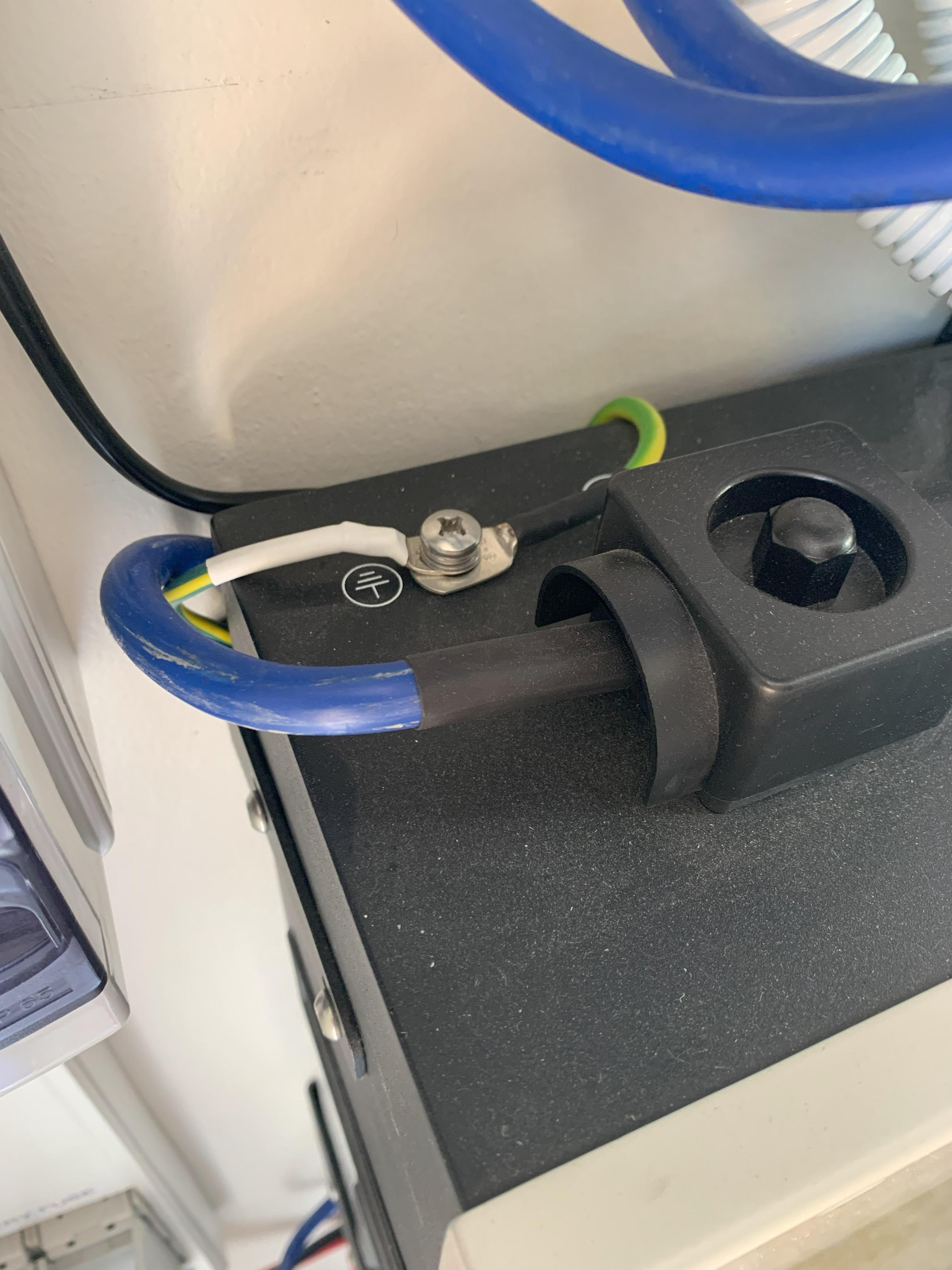
Correct - the casing must be earth'd (example in Picture)

-
@HendrikBigChief, thanks for the insights 👍
-
Thanks @I84RiS and @WannabeSolarSparky - I did not think this was correct, but always best to check.
-
Since I have installed my own Solar System (Deye 8kw, 24 Canadian Panels (10360w) and 2 x Dyness 5200 batteries), I wanted to ensure I was compliant by obtaining a CoC. I have previously obtained a CoC for my Eskom Board, including my Inverter installation, but that was before I installed Solar and from what I understand, you need a CoC for all Solar installations as well. So, I contacted a guy who is apparently a certified/registered electrician and is also Solar certified (has a PV green card) and provides Solar CoC’s, and according to him, the ECA Rules (Electrical Contractors Association) has the following requirements: https://ecasa.co.za/technical/pv-installers-must-be-electrical-contractors/ · AC and DC cannot run in the same conduit · All MCB’s (Micro Circuit Breakers) must be correctly sized for both Grid & Load · Each Solar Installation must have a separate Earth spike which must read less than 10 ohms (if not then add a 2nd or 3rd spike approx. 1m away and join them) - The DC DB / Combiner box / Solar Panels would be connected to this newly installed earth spike · Every Panel must be joined to the next panel by 6mm earth wire (you cannot just earth the Rails) · You must run the positive (Red) wires in a separate conduit and must include the earth in that conduit. If you have multiple strings and have separate conduit for each strings positive wire, then you must include the earth wire in each conduit. · Within the Combiner Box, you need to fit Bootlace Ferrules at the end of each Solar wire (stranded wire). This is required for both single wires (single wire bootlace ferrule) and where 2 wires are going into a MCB (twin wire bootlace ferrule) · For your Inverter installation (Grid and Load connections), you cannot just use the earth wire (normally a single copper wire) contained within the flat Twin & Earth wire, as this is normally thinner than the actual load carrying wires (e.g. 6mm or 10mm). To be compliant you would need to run a separate earth, which is the same thickness as the current carrying wires, between your Main DB board as well as your Essential DB board. · For your Inverter connections (Grid & Load), the earth of the Load input (in the inverter) must be bridged (I presume bridged to the Grid earth). From what I was told, if you do not do this you may have a floating voltage between Neutral & Earth especially prevalent during load shedding) · Your Inverter casing must be earthed to this same earth · Your batteries must also be earthed to this same earth As a learning to myself (and others reading this post), I would like to ask the forum if the above is correct and if there are any other requirements that have been omitted? Thank You
-
I have an existing installation which consists of a Deye 8kw Inverter, 24 Canadian panels (totalling 10360w) and 2 x Dyness 5200 (5.2Kwh) batteries. My intention is to add 2 x additional Dyness 5200 batteries, in a staggered manner, over the next few years. In a conversation with a colleague, he was informed that adding "new” batteries to an old installation (to an existing bank of batteries) will degrade the “new” batteries. Is this correct?
-
I have been looking at a couple of my friend’s combiner box installations and have noticed wiring differences between them. Further to this I have searched online and found a number of pictures where the wiring is also different (see pictures below). This has made me question what the correct way would be to wire a combiner box and if there is a set standard? So, what is the correct way? From what I can make out through numerous searches, one solution is for your incoming positive & negative wires (from the solar panels) to each go into a Fuse Holder and then into the top of an isolator which doubles up into your SPD. The bottom of your Isolator then goes to your Inverter - I have posted a stick drawing of this below as Option 1 and an alternative as Option 2. Are any of these correct and if not, what would be the better/preferred way? Note: The hardware (fuses, Isolator & SPD) is also very different between installations - I have posted these questions under a different thread: https://powerforum.co.za/topic/24599-how-to-correctly-size-solar-combiner-box-components-fuses-isolators-spd%E2%80%99s/


-
I have been looking at a couple of my friend’s combiner box installations and have noticed that there is no standard in the components used and it seems that the installers just use what they have on hand or can get hold of at the time. So, the question is, how would you size your combiner box components (I.e. Fuses, SPD’s and Isolator MCB’s)? Thinking out loud, and ignoring inverter specs (I.e. Max PV Input, MPPT Input Range and PV input current) for the sake of this discussion, would it be correct to start by looking at the Solar Panel specs (I.e. Operating Voltage (Vmp) and Open Circuit Voltage (Voc) as well as the Operating Current (Imp) and the Short Circuit current (Isc))?. As an example, looking at the Canadian 545w panel specs (see picture) you have the following Solar Panel specs: · Vmp = 41.5v · VoC = 49.4v · Imp=13.14A · Isc = 13.95A Ignoring possible future expansions, would it be correct to say that for a single string (no paralleling) of say 10 panels in series ( 494Voc / 13.95A Isc ), I could use a 15A or 20A solar fuse on each line (Positive & negative) and a 500V/15A Isolator as well as a 500v SPD? Then if I wanted to double the number of strings (parallel 2 strings so the specs would be ( 494Voc / 27.9A Isc), I would change these slightly and use a 30A solar fuse on each line (Positive & negative) and a 500V/40A Isolator as well as a 500v SPD. Would the above work and I suppose getting back to the original question, is there a correct way to size your components based on each installation (What would the correct specs be and how would one calculate what components to use)? Any insights would be appreciated. Thanks

-
This is awesome feedback - thank you @Steve87 & @Scorp007. @Steve87, this is a seriously impressive installation - so pleasing to see that some still take pride in their work in SA - well done to you and your team.
-
Hi, I have good friend who has a solid concrete roof on which he wants to install 4 x rows of 6 x 550w solar panels using A-Frames. The main point here is that he does not want to drill into the roof and would prefer to use Concrete ballasts to hold the A-frames down. Can anybody advise how much ballast (weight) he would need to use per A-Frame to hold the panels in place (not to blow away in the wind). He stays in Cape Town where the wind is gusty and can be relatively stong, especially when the South Easter blows. Below is a picture of the A-Frames he wants to use (note: this is not a picture of his installation....just a picture of the A-Frames) The A-Frames will be placed 1.2m apart - can anyone advise how much weight is recommended per A-Frame?

-
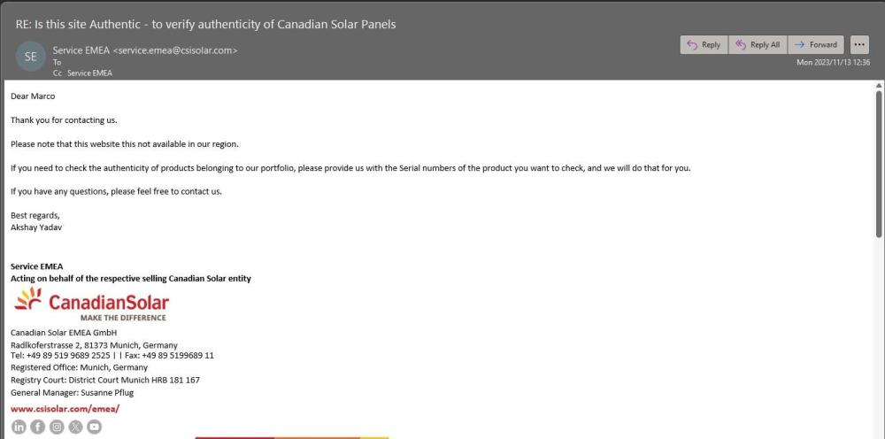
I received feedback from Canadian Solar EMEA, as per the picture below: Looks like the website I was provided by a supplier does not work in our region - so if you need to check the authenticity of Canadian Solar Panels, best to email Canadian Solar EMEA with the Serial Numbers and ask them directly - they should respond as they responded to me, but it may take a day or 2. Good to know for future 🙂 M
-
Hi, With so many stories of knock-off panels being sold under brand names in South Africa, I was wanting to know if there was a way to verify the authenticity of Canadian Solar Panels before actually purchasing them. I tried to contact Canadian Solar in Cape Town (Canadian Solar South Africa (Pty) Ltd | 021 001 4800 | Letterstedt House, 4th Floor, Newlands on Main, Cnr of Campground and Main Roads, Newlands, 7700), but no-one answers the phones, and you are ultimately directed to record a message. I also tried to contact CSI Solar internationally over the weekend but have not received a response as yet. I was subsequently given the following website, which is in Chinese (your web browser should be able to translate to English), but I am not sure if this is legit: https://snquerycn.csisolar.com Does anyone know if this is a legit site or if there is any other way to verify the authenticity of Canadian Solar Panels (or other brand's). Thank You Marco
-
This makes sense - thank you @greenfields & @scorp007. This was an excellent discussion, where general information is limited, and I for one have definitely benefitted from the insights provided. Hopefully others will also learn/benefit ...
-
Thank you, although perhaps I need to clarify my question - when would one consider the PV Input Voltage and when would you consider the MPPT Input range as both refer to voltage but have different ranges? So, the question is what is the difference and when would you use/consider each metric? The same question would apply to PV Input Current and a Max PV Isc ? Any insights into the difference and when you would consider each metric would be awesome?
-
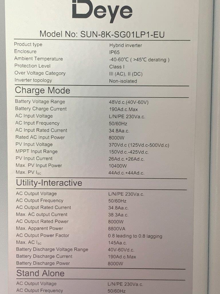
I do have 1 last question which I touched in this discussion although not really related to it: Can anyone explain the difference between the following Inverter specs (Deye 8K Inverter as an example): PV Input voltage (125vdc - 500Vdc) and MPPT input range of (150vdc-425Vdc) and PV Input Current (26Adc+ 26Vdc) and a Max PV Isc (44Adc + 44Adc) Both either refer to voltage or Amps - which do you consider when?
-
Thank you @Scorp007 and @Taliab - considering I want the best (safest) possible solution, this makes perfect sense. From what I understand - both the scenarios would work: Option 1: I could have a 3rd combiner box (so each string has its own fuses, isolator and SPD) and then parallel the 2 strings for MPPT1 at the inverter (this would be an excellent solution but will not be the most cost-effective way) or Option 2: I could save on the 3rd combiner box by paralleling the 2 strings MCB for MPPT1 (in the combiner box) - the MCB's, fuses and SPD already exist so there would be no need to purchase additional hardware (fuses, isolators and SPD). From what I understand, I can still then have a single 6mm wire going from my combiner box to the Inverter as the Amp rating would suffice (I've read that the Amp rating, dependent on distance, is > 30A at 15m) - so a perfect solution. Thanks for your valuable insights - I have got some awesome learnings from this discussion and hopefully others will too.
-
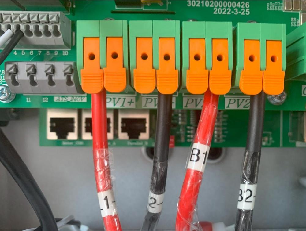
Thanks everyone for your valued insights - the learnings have been awesome - thank you. I have formulated an updated config, using all my existing panels (16 x 375w panels) and 8 x "new" 550w panels, which I believe maximises my solar panel production, mindful of my inverter specs (Inverter Specs for Deye 8k Inverter [SUN-8K-SG01LP1-EU]: Max PV Input power = 10400w, PV Input voltage = 125vdc - 500Vdc, MPPT input range of 150vdc-425Vdc, PV Input Current of 26Adc+ 26Vdc and a Max PV Isc = 44Adc + 44Adc) This updated config (see pic below) would give me: 10400 watts Max PV power (at max power) MPPT1 = Max 6000w using 2 x strings of 8 x 375w panels in each string, with a VoC of 346.76v @ 3 degrees ambient temp and an Isc of 23.22A MPPT2 = Max 4400w using 1 string of 8 x 550w panels, with a VoC of 419.50v @ 3 degrees ambient temp and an Isc of 14A As long as there is no issue with the MPPT's being different (from a watt's perspective), this hopefully would maximise my production? Note: Cape Town has never dropped below 3 degrees ambient temperature) If this looks ok, I do have a question regarding MPPT1 and the joining (paralleling) of the 2 strings (each using 8 x 375w panels) - is it best to combine these strings using a MC4 "Y splitter" (see pic) on the roof and then having one 6mm cable going to my inverter (through a combiner box)? or Is it best to run a separate cable for each of the 2 strings, through their own separate combiner boxes each with fuses, isolator switch and SPD, and then into the inverter using the 2nd PV port available on the inverter (see Inverter picture below - PV1 has 2 ports for + and - and PV2 also has 2 ports for + and -)? Does this updated config look ok and if so, what would be the "best" way to parallel the 2 x strings on MPPT1? Any insights would be appreciated... CS-Datasheet-Hiku_CS3l-375MS.pdf CS-Datasheet-HiKu6_CS6W-MS_v2.2_F30_F35A_EN_530-555W.pdf


-
Thanks @TaliaB, @Greenfields and @Scorp007. I have come up with the following configuration which I think is best suited for my install, while being mindful of the space I have available (panels need to be smaller than 2.1m tall) as well as my inverter specifications as follows: Inverter Spec for Deye 8k Inverter [SUN-8K-SG01LP1-EU] Max PV Input power = 10400w MPPT input range of 150vdc-425Vdc PV Input current of 26Adc The below configuration (see picture) would give me: 9390 watts Max PV power MPPT1 = Max 5250w using 2 strings, with a VoC of 305.66v and a Isc of 23.22A MPPT2 = Max 4140w using 1 string, with a VoC of 396.8 and an Isc of 14A From what I can see, I cannot add a 10th panel to MPPT2 as this would increase my 'VoC' above the target range of 425Vdc and I cannot split MPPT2 into 2 strings and parallel them as this would place my 'Isc' above the 26Adc. I also cannot go to a larger panel (e.g. 545W panel) as my roof simply is not big enough to take 2 x 2.18m panels. Do you see any issues with this config? CS-Datasheet-Hiku_CS3l-375MS.pdf CS-Datasheet-HiKu6_460MS.pdf IMG_2263.HEIC