


weber
Members+
-
Joined
-
Last visited
Everything posted by weber
-
Hi seant. There already is a time delay. What we're doing is in addition to that. We could have just increased the time delay but that could lead to battery abuse.
-
Hi Javi. I must point out that we do not have resources to provide patched firmware for 24 V Axperts. But your data is still valuable. Thanks. As mentioned in the fine print above: We hope to estimate the internal resistance as k * ([26] - [27]) / [2], where k is a dimensionless constant close to 1. So what I'm doing with the data provided, is calculating the ideal value of k for each system as follows: k = kettle_volt_drop / kettle_current * [2] / ([26] - [27]) In your case we have k = 1.41 / 121 * 70 / (28.7 - 28.0) = 1.2 In my case k = 1.6. From other systems I have k = 0.9 and k = 1.6. These are all LFP systems. It would be good to have some numbers from lead acid systems, and from very large and very small systems. I can see already, that a single fixed value of k is not going to be very satisfactory, but it is way too much work to patch the firmware to add new parameters, because you must find space in EEPROM for them, and arrange for them to be saved and restored and communicated between parallel machines, and you must provide an LCD interface and serial commands to set and read them. So what I am working on now is using the least significant digit of the cutoff voltage (parameter [29]) to choose between 5 different values of k, which can be considered the strength of the voltage-threshold compensation. Something like this: .8 or .3 for weak (k = 0.8) .9 or .4 for medium weak (k = 1.0) .0 or .5 for medium (k = 1.25) .1 or .6 for medium strong (k = 1.6) .2 or .7 for strong (k = 2.0) So at worst, you might have to choose a cutoff voltage that's ±0.2 V away from the exact voltage you wanted, so as to get the compensation strength you want. I note that it's best to err on the side of weaker compensation. If it is stronger than you need, you will end up abusing your battery. But I need data from more and different systems so I can choose a suitable set of 5 values for k.
-
Here's an example from my own system (5 kWh of LFP). Settings: Abs [26] = 55.2 V, Flt [27] = 53.7 V, Tot [2] = 100 A. Before kettle 52.7 V, 0 A After kettle 51.7 V, -42 A
-
Hi Gabriel. So which of those two names do you prefer? You don't need to do any math. You can help us to help you by just telling us your battery voltage and current, immediately before and after turning on your kettle. And tell us your settings [26], [27] and [2] (absorb voltage, float voltage and max total charge current). Please start the ball rolling in the new thread, here: https://powerforum.co.za/topic/2544-axpert-kettle-voltage-sag-data-request/
-
As Coulomb mentioned, we have been working on a set of firmware patches to address the "kettle cut-off" or "premature source switching" problem. He also mentioned that we had a major setback when we bricked an inverter in the process. But as of today, I am testing the first working non-bricking development version (YF1_73.00e). Hoorah! But there are some aspects of it that I'd like to run past you gentlemen. First, we can't decide whether to call this feature KettleKomp™ or AussieBrew™? Second, we're not sure how well it is going to work on all the many and varied Axpert systems out there. The math challenged can skip the fine print below. We currently calculate: voltage_threshold_compensation = battery_current * guestimated_internal_resistance where guestimated_internal_resistance = k * (absorb_voltage_setting[26] - float_voltage_setting[27]) / max_total_charge_current_setting[2]. where k is a constant. I tried k = 1 and it was too low, at least for my system. I'm now trying k = 2. When there are parallel or phased machines, battery_current and max_total_charge_current_setting[2] are summed over all machines. We're trying to avoid having to provide a user interface to allow setting the internal resistance, as this would be very difficult. This formula is based on the idea that at least some part of the difference between absorb and float voltage settings is due to the internal resistance of the battery causing voltage rise at the maximum charging current. We're asking axpert owners to help us by telling us how many volts (including tenths of a volt) your battery sags by, when you turn on your kettle (or other heavy load); what battery current your kettle draws; and what your values are for settings [26], [27] and [2] (the latter summed over all machines).
-
You're almost contradicting yourself here. i.e. I was tempted to say, "Either they cloned badly or they cloned well. You can't have it both ways." I think Wolf51's guess is more likely to be true. i.e. that these were manufactured by Voltronic, but have failed and been poorly repaired by someone.
-
I wouldn't assume those are made by Voltronic. Voltronic Power Tech is a Taiwanese company with factories in mainland China whose product is sold under many brands. But there is also at least one mainland Chinese company that is making poor quality look-alikes. One such brand is "Must". "Sunray" may be another. AFAIK Voltronic doesn't have any factory in Foshan. See http://www.voltronicpower.com/factory.php Gotta love the stirring music and those Chinglish captions. You should at least watch the boardroom presentation scene from 3:55 to 4:47, then check out what (or who) they were really talking about, here: http://forums.aeva.asn.au/viewtopic.php?f=64&t=4332&p=59963#p59963
-
Oops! I failed to give the link to the old draft standard. Here it is: http://southerngreenenergy.com.au/wp-content/uploads/2013/01/DR_AS_NZS_5033_Installation_and_safety_requirements_for_photovoltaic_PV_arrays.pdf This forum allows way too short a time for edits. On the AEVA forum we don't have a time limit on edits at all. This has never been a problem.
-
I just noticed another difference from the present release version of the Australian standard. Option 3.3.5.1 (b) is only allowed if I_mod_max_ocpr > 5 x I_sc_mod, i.e. only if the manufacturer's max series fuse size is more than 5 times the panel's short circuit current. This never happens, so you can ignore the (b) option. Also see section 4.3.10 regarding blocking diodes on PDF page 33.
-
That's good @phil.g00 To help you in your deliberations, you may be interested to know that in most jurisdictions, string overcurrent protection for (what usually works out to be) 3 or more strings in parallel, is not merely considered a good idea, but is a legal requirement. The best I could find online for free is this old draft version of AS5033, the Australian standard for PV arrays. Because of course, it's all about safety, so you have to charge people AU$254 to read the real thing! Start with section 3.3 on PDF page 21 and read through to at least the end of section 3.3.5.1 (a) on PDF page 22. You may also want to see the definition of I_mod_max_ocpr on PDF page 9. It's what the panel manufacturers usually call "maximum series fuse rating". And you can see a circuit diagram on PDF page 16. I expect the corresponding South African standard has almost-identical requirements. I noticed one difference from the present release version of the Australian standard. In 3.3.5.1 (b) the first occurrence of "(n_g - 1)" has been corrected to just "n_g".
-
You can install a diode per string. But you also need a fuse per string in case the diode goes short. But only if you have 3 or more strings in parallel.
-
@phil.g00 Once again I failed to understand the exact nature of your misunderstanding. Sure, if the diode was in series with the current source, it would necessarily be forward biased in normal operation. But if you had just googled the equivalent circuit, you would have seen that the diode is in parallel (or rather anti-parallel) with the current source, not in series.
-
Hi @NigelL Phil didn't suggest "a couple of MCBs". He only suggested one MCB, to protect the cable to your panels from your batteries. That protection is necessary too. But Phil would have you connect your 3 strings in parallel with no over-current protection between them. It was I who suggested three MCBs (one per string), as a (convenient but expensive) alternative to a pair of fuses per string. And if you have your individual strings protected in your DC-DB on the ground, then these 3 fuse-pairs or breakers also provide protection of your cables against current sourced from your battery, e.g. via a faulty SCC. There is a first line of defense against nearby lightning that should be done on all jobs and costs nothing. That is to minimise the loop area enclosed by your PV cables, so they don't act as an antenna for the electromagnetic pulses. Think of twisted-pair cables, although you don't need to actually twist them. Hi @phil.g00 You're still missing something. But this time you're in good company because @plonkster is missing it too. And that is: Although PV cells are indeed silicon diodes, they point in the opposite direction to what you're claiming. They are forward biased in normal operation. Don't take my word for it. Google "solar cell equivalent circuit" WoTQ. Or better still, do the experiment. Connect a string of two solar panels (or a current-limited power supply of a similar voltage) in parallel with a single panel, all out in the sun. Then measure the current. Because they are forward biased in normal operation, they will be even more forward biased in a string fault scenario. Hence the need for the fuses when there are 3 or more strings in parallel. You claim that blocking diodes would be better protection than fuses. But you also mention that diodes can fail short circuit. I hope you can see that those two things can't both be true. An overcurrent protection device that can fail short circuit is no overcurrent protection device at all. Blocking diodes can be used, but they still need to be backed up by fuses if you have 3 or more strings in parallel.
-
It's getting crowded in here. @phil.g00, you seem to be missing the fact that in this case there are three strings in parallel. So if any group of cells gets shorted out, e.g. by a failed bypass diode, then the remaining cells in the same string, will have current forced through them in reverse, by the two healthy strings. Sure PVs can take the same current in reverse as they can deliver in the forward direction (into a short-circuit), but they can't usually take twice that current. So with only two strings in parallel you don't need string overcurrent protection, but with 3 or more strings in parallel you do if you want to avoid a possible fire. How you size that protection is, first you read the panel data sheet and see what the max fuse size is that the panel manufacturer recommends. Failing that, you take the panel's short circuit current under standard test conditions (Isc) and multiply it by 1.5. You then use the next standard size above that, which must be less than 2 times Isc. We used to use 1.25 * Isc in Australia, but there were still some nuisance trips, hence we now use 1.5 * Isc. That factor has little to do with temperature. PV short circuit current is hardly affected by temperature. It is however proportional to irradiance. During the sky condition known as "cloud halo" it is easy to get 1.25 suns worth of irradiance (i.e. 1250 W/m²) due to direct sunlight plus diffuse light from white cloud surrounding the sun. Yes. Best not to have these protection devices on the roof. But if your installer refuses to do anything else, he could at least use inline weather-proof MC4 fuses tied up underneath the panels. When it is done on the ground, there is also the option to use a double-pole non-polarised DC circuit-breaker for each string (instead of fuses). This costs more but has the advantages that (a) you can see if one has tripped, and (b) you don't need a separate isolation device. I use NoArk brand.
-
Yes. There is a manual in the 73.00c zip file you downloaded. You can also see it here: http://dkeenan.com/AussieView Manual.txt
-
Man! That thread was painful to read. Talk about the blind leading the blind. Not plonkster. He knows whereof he speaks and speaks whereof he knows. And not Jaco de Jongh. He does experiments to find out what actually happens. Some corrections: 1. 3.29 V per cell is too low as a float voltage setting for LFP. You could end up with only about 70% left in your battery at sundown. 3.35 V per cell is a better choice. 2. A PV panel can't be modelled as a current source in parallel with an ideal diode. That would give open circuit voltage that was either zero or infinite, depending which way round you put the diode. A PV cell however can be modelled as a current source in parallel with a real silicon diode. The diodes shunt all the current when the panel is open circuit. 3. There are no series protection diodes in solar panels, intrinsic or extrinsic. Only parallel diodes, called bypass diodes, that allow current to bypass one third* of the panel if one or more cells in that third are shaded (* in 60 or 72 cell panels).
-
We've just added a new feature for pf1 models with the 64 V option. Dynamic Load Control. That bumps us to beta 72.20c.
-
Coulomb and Weber have just posted a new beta version of their patched firmware with AussieView™ and Dynamic Current Control. This one is 72.20b for Axpert MKS 5K-48 PF1 models with the 64V option.
-
The material is so thick, I'm thinking it has to be aluminium. Sure heat would soften it, given time, but something still had to push it upwards, and thereby pull the tops of the sides towards each other. Notice there are no screws near the middle of the lid at the back.
-
I don't know any more than what I posted. But those cells must have gone off with a hell of a bang to bow the lids like that.
-
Kilowatt Labs "supercapacitor" fire, before and after photos here: http://forums.aeva.asn.au/viewtopic.php?p=69713#p69713
-
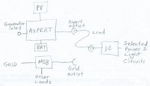
Here's my suggestion for what I hope is a legal way of wiring an Axpert in South Africa without requiring an engineer's report, only an electrician's certificate. If the battery goes flat or you need to do maintenance on the Axpert, you can just move the lead from the Axpert outlet to the grid outlet. No problem. Now some of you are bound to think, "What's to stop me running a lead from the grid outlet to the Axpert's generator inlet?". The answer is, "Fear of getting caught", because it would be illegal.
-
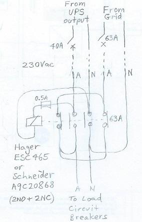
Ebrsa, here is how our changeover contactors are wired. But you won't be allowed to do this with the Axpert, as explained by plonkster here: https://powerforum.co.za/topic/2109-is-your-system-legal-capetonians-have-till-28-feb-2019-to-register-their-systems/?page=4&tab=comments#comment-37792
-
They did indeed have certification as a UPS. At least under the MPP Solar brand (as the PIP-4048MS). That's the Axpert MKS 5K-48. http://www.mppsolar.com/manual/CE/EMC-PIP%204048MS%20report.pdf http://www.mppsolar.com/manual/CE/LVD-PIP%204048MS-report.pdf Plonkster's totally right about the term "off-grid" inverter meaning simply "not capable of feeding power into the grid", no matter whether it is actually on the grid or not. That usage is pretty much forced on us by the poor choice of the terms "grid-tied" and "grid-connected" to mean "capable of feeding power into the grid". Although one alternative is to call them "stand-alone" rather than "off-grid" inverters. And the others should have been called "grid-feed" inverters.
-
Hi SilverNodashi. I don't understand how you got any of that from what I wrote. It is only the draconian South African regulations that make Axperts (nearly) useless as on-grid solar UPSs. They are still perfectly good off-grid inverters, even in South Africa. In that case the AC input is for backup from a fuel generator.


