Wiggly Electron
Members
-
Joined
-
Last visited
Everything posted by Wiggly Electron
-
That's great news! A lot easier than to make a filter!
-
This sounds like a low frequency hum. It isn't directly related to the 15kHz noise discussed earlier in this thread. I'm afraid there isn't much you can do about it unless the unit is in fact faulty and you can get it replaced. But based on what I have heard it's quite common for these inverters to make that noise.
-
Hi @starmage What kind of buzz is coming from your inverter? A 50Hz hum or a 15kHz high pitched wine?
-
Repost from another thread: https://powerforum.co.za/topic/12943-sunsynk-8kw-high-pitched-noise-beware/page/3/ Hi all Here is the update on how to make your own inductor to filter out the noise coming from the inverter. First off, you will need a core to wind your wire around. A toroidal core will be the easiest to work with and will also radiate the least amount of EMI. The bigger the core, generally speaking, the better as you will be able to get more windings on it with a thicker wire. Here is the biggest one I could find with a good permeability: https://www.mantech.co.za/ProductInfo.aspx?Item=82M1485 The enamel wire diameter will determine the amount of amps it will be able to handle. I would recommend using 1-1.6mm diameter wire. You can find a good variety from Communica. https://www.communica.co.za/products/eccw-1-25 Just note that thicker wires will be more difficult to work with, but will obviously be able to handle more current. Here is a website to give you an idea of the current carrying capability of different wire thicknesses: https://www.powerstream.com/Wire_Size.htm How many turns do you need? Well you would want to wind the inductor to get you an inductance of at least 1mH, but more than 5mH would probably be overkill. You can calculate the exact number of windings you'll need with a nifty program called Coil64: https://coil32.net/download-coil64-for-windows.html For the above-mentioned core and wire, you will need about 50turns to get 1mH and 75turns for 2mH. (The inductance goes up with the square of the number of windings and the resistance of the wire goes up linearly with number of windings). As mentioned before, you would place this filter "In-Line" by breaking either live or neutral and join the break through the inductor. Also, be sure to use a surge protector on the load side of the filter as inductors might cause voltage spikes when the current draw through it changes. I still need to test my toroidal filter to see how many amps it can handle, but for now I can definitely say that it works in filtering out the noise to a level that is completely inaudible. The previous filter I made with the E-core handles 8 amps without getting too hot. I would guess that the smaller toroidal core will do about 3 amps, as I had to use a thinner 1.25mm wire instead of the 2mm wire. Hope it helps!
-
Hi all Here is the update on how to make your own inductor to filter out the noise coming from the inverter. First off, you will need a core to wind your wire around. A toroidal core will be the easiest to work with and will also radiate the least amount of EMI. The bigger the core, generally speaking, the better as you will be able to get more windings on it with a thicker wire. Here is the biggest one I could find with a good permeability: https://www.mantech.co.za/ProductInfo.aspx?Item=82M1485 The enamel wire diameter will determine the amount of amps it will be able to handle. I would recommend using 1-1.6mm diameter wire. You can find a good variety from Communica. https://www.communica.co.za/products/eccw-1-25 Just note that thicker wires will be more difficult to work with, but will obviously be able to handle more current. Here is a website to give you an idea of the current carrying capability of different wire thicknesses: https://www.powerstream.com/Wire_Size.htm How many turns do you need? Well you would want to wind the inductor to get you an inductance of at least 1mH, but more than 5mH would probably be overkill. You can calculate the exact number of windings you'll need with a nifty program called Coil64: https://coil32.net/download-coil64-for-windows.html For the above-mentioned core and wire, you will need about 50turns to get 1mH and 75turns for 2mH. (The inductance goes up with the square of the number of windings and the resistance of the wire goes up linearly with number of windings). As mentioned before, you would place this filter "In-Line" by breaking either live or neutral and join the break through the inductor. Also, be sure to use a surge protector on the load side of the filter as inductors might cause voltage spikes when the current draw through it changes. I still need to test my toroidal filter to see how many amps it can handle, but for now I can definitely say that it works in filtering out the noise to a level that is completely inaudible. The previous filter I made with the E-core handles 8 amps without getting too hot. I would guess that the smaller toroidal core will do about 3 amps, as I had to use a thinner 1.25mm wire instead of the 2mm wire. Hope it helps!
-
Hi all I finally received some toroidal cores. As soon as I get the enamel wireI that I ordered, I'll wind a new filter and test it. Should be a few days to a week before another update.
-
Hi all There are two other posts on the same topic that is worth reading if you are still looking for a solution. These post are for Sunsynk inverters, however I believe the internals are the same. Kind Regards Wiggly
-
Hi @DiSiNTiGR8 Most of these off-the-shelf filters are not very likely to work unfortunately. I have wasted a couple of bucks to try these out too. Almost all of them are designed to filter out frequencies in the CRISPR defined conducted emissions band, which starts from about 150kHz and ends at 30MHz. Some do seem to have good filtering properties at 15kHz on their datasheets, but one should be careful for the "50Ω/50Ω symmetrical" condition the tests were run at. This condition refers to the characteristic impedance (transmission line theory) of the test system and is usually only applicable to RF circuits and not mains power. The test condition for an inverter would be closer to something like 0.1Ω/100Ω. Under this test condition most of these filters perform very poorly or can even cause resonances making the problem worse as in you case. If you are looking for an off-the-shelf solution, you should get a filter with an inductance in the 1-5mH region (the higher the better but past 5mH it would be overkill). Just be careful, some datasheets also list the Common-Mode inductance, which wont be helpful in our case. A differential inductance (aka a normal series inductor as everyone knows it) is needed. I am yet to find an off-the-shelf solution that has a large enough inductance and current rating. Usually you get to pick either or, but not both. Regarding a DIY solution, I am looking for a supplier of a large toroidal core, which will make the whole winding process very easy. This will make it a viable solution for the general hobbyist. Will make a post as soon as I find something. Cheers for now Wiggly
-
Hi @scot These filters won't work for filtering out the Sunsynk's noise. The 10-15dB attenuation you see on the datasheet is for a 50/50Ω impedance system (traces A and B on the log graphs). A 50/50Ω impedance system is typically what you would see in radio and other RF circuits. The trace you should be looking for is trace C, which is a 0.1/50Ω system which is approximately what you would have with a 5kW inverter setup. In this case the filter would cause a negative attenuation (also known as a gain) of about 6dB. This filter would therefore make the noise even worse due to constructive resonances in the filter! 6dB would translate into a doubling in noise amplitude at 15kHz😵 There is another post here on powerforum where a better performing solution is discussed. DiSiNTiGR8 has linked it in the post above. Cheers Wiggly
-
This is usually not something that can be changed with a software or firmware update. Even if it could, it wouldn't be advised as the components that the engineers chose were specifically chosen to work at 15kHz. Changing the switching frequency might damage the components or cause efficiency problems.
-
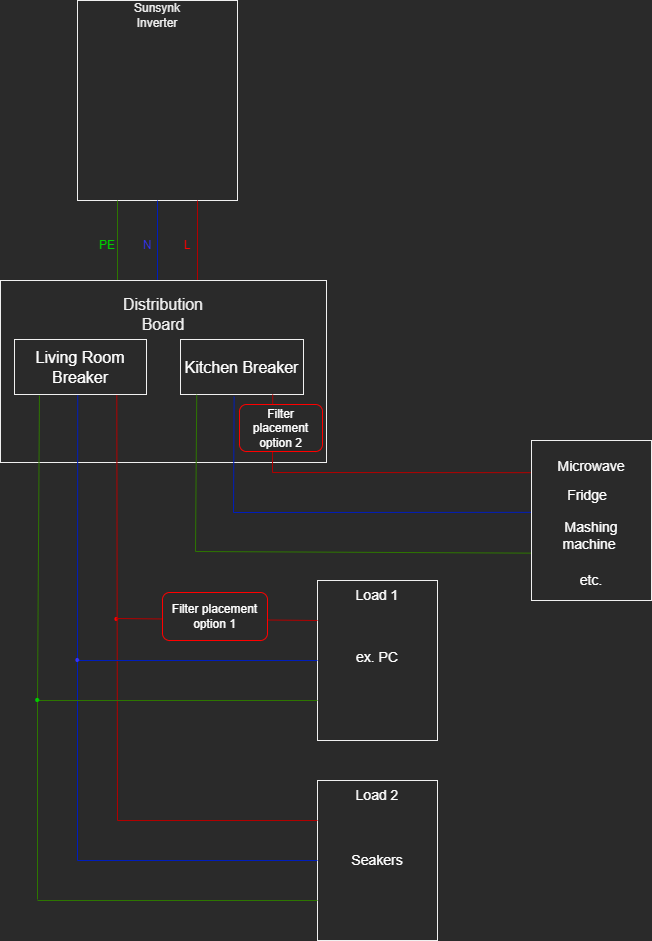
See the attached diagram I made below. You can have the filter in multiple locations but I would recommend the placements I marked as options 1 and 2. Option 1 will be the easiest to implement as it will require the smallest inductor (as it will have a smaller current requirement). The downside is that it will only silence that specific appliance that is connected right after it. Option 2 will be more expensive and also more difficult to build as it will need thicker wire due to a larger current requirement. The upside is that it will cover an entire room's (or multiple rooms') appliances. The surge protector should be placed between the filter and the load in both options. An inductor has two wires, so you would cut the live wire and join it again with the two inductor terminals. For option 1 I would recommend a simple Ellies surge protect plug: https://www.takealot.com/16a-high-surge-protection-3-pin-plug-top-for-electrical-devices-/PLID73912362 https://www.takealot.com/high-surge-protection-8-way-multi-plug-with-r30-000-warranty/PLID27971525 For option 2 I would recommend a DIN rail mount surge surge protector to be installed in the distribution board. I couldn't find one online from a reputable retailer now but they usually sell them at general electrical suppliers such as ACDC Electrical. They look something like this: https://www.chamberlains.co.za/lear-din-10-20ka-2-pole-surge-protector-385v-blsd-10-2-1086674 I will make a post that details the technical and practical inductor design later on this week. For now I'm a bit swamped with work. Hope it helps!

-
My situation is a bit different; My flat is being fed from my landlord's house with two 5kW Sunsynks in parallel. I have also used an app called "Sound Analyzer" by nobapp (the free version is Sound Analyzer Basic I think). It works quite well in picking up the more subtle noise emissions or emissions in noisy environments. Sometimes something like fan noise will drown out the 15kHz noise from the ear, but with the app you can clearly see it. In my experience I always hear the 15kHz noise, even during night time when the solar DC/DC isn't doing anything. The noise would seem to come from any appliance with a transformer in it (which is the same as @mneeth suggestion as the appliances having some form of inductance in it). I believe the magnetic field created by the noise induces Eddy currents in these components which then vibrates the enamel wires or the core at said frequency. The appliances where I noticed it the most was my UPS, inverter microwave, laptop charger, inverter fridge and inverter washing machine. Some sound worse than others.
-
Hi there When looking for a filter in this application it's all about inductance. The bigger the better. If you look at the specs of this ferrite sleeve it is specced to be 225Ω @ 100MHz. So if we use the formula Z=2πfL we can solve the inductance to be 358nH. That is very, very small when trying to filter 15kHz. At this frequency it will only offer about one thousandth of a decibel of attenuation (0.001dB). Or in simpler terms it will only filter 0.02% of the noise we are struggling with. These sleeve ferrites are designed to filter out much higher frequencies in the AM and FM radio bands. The design issue with these inverters are very unfortunate. I believe most inverters have similar noise emissions, although at slightly higher frequencies that are out of the hearing range for humans. I have measured an Axpert 5kW VMIII and it had similar noise levels but only at 19.5kHz which is basically inaudible. The problem with the Dye/Sunsynk inverters are that their switching frequency is just a bit too low at 15kHz where we can hear it. I am still on the lookout for more off-the-shelf solutions, if I stumble across anything I will be sure to post it here. Regards
-
Both will work. However it will probably be best to use multiple filters on different plug lines to distribute the load across multiple filters. If you are only going to use one filter on the main live inverter output, it's going to be huge! Alternatively (probably the best option) is to use one filter just before the appliance that causes the most frustration. That way you can keep the size and cost of the filter down. Oh an an important note, the inductor can cause big voltage spikes when a load switches off. It is best to add a surge protector on the appliance side (or both sides if possible). So the setup would be Inverter/Filter/Surge Protector/Appliance.
-
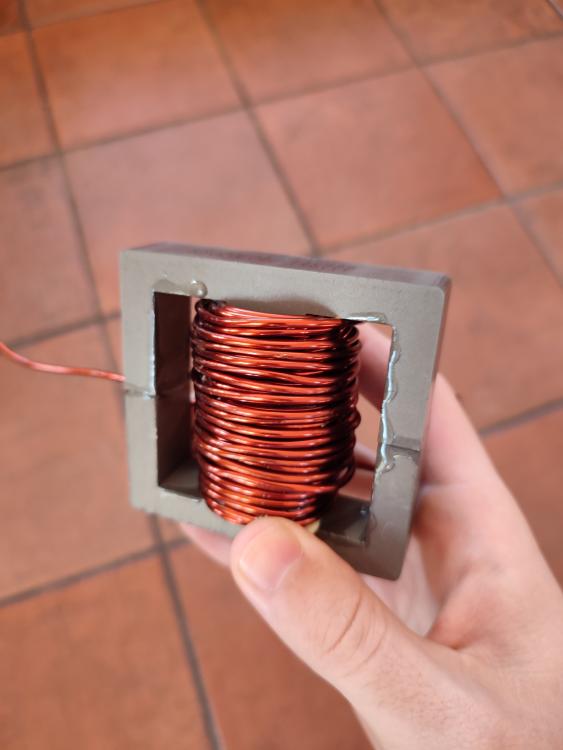
Hi everyone I have found a solution to the problem. Before you get too excited, I need to say that it isn't an easy nor cheap fix. It also only gets rid of the 15kHz whine on your appliances (output side of the inverter), while the noise from the inverter itself remains unchanged. That being said, it was still worth it for me. Our microwave was driving me insane! Anyway without further ado, to fix the issue you need to place a big filter inductor on the live line between your inverter and your appliances. The inductor must have a ferrite core (preferably the MnZn type as they have a higher core saturation point). Iron cores wont work as they will filter out the 50Hz power as well and probably cook itself within minutes. I got my E-cores from Mantech Electronics (about R350 for two half cores), although they seldom have stock of these large cores. With these cores you will need between 50-100 turns (resulting in 1-5mH) and the wire size is determined by the amount of current your load is going to draw. I used 10m of 3.14mm^2 enamel wire (sourced from Communica @ R210) which got me about 50 turns and 1.25mH. At 1.25mH it should attenuate about 14dB of the 15kHz noise. After I installed it, I couldn't hear the whine at all. So it definitely works. Also, another note to those who haven't wound an inductor/transformer yet, it took me a whole day to wind that thing. A solid core wire with a 2mm diameter is quite difficult to work with... Hope this might help someone. Regards
-
Thanks for the pdf docs Rikus! It definitely makes it more clear what the comms cable is doing. I have received a comms cable with my inverter so it was as easy as plugging the one end in the CAN of the pylontech and the other end in the battery comm port of the inverter. If you would like to make your own cable you could reference the pylontech battery for a pinout. Cheers
-
Hi all I was wondering what information Pylontech batteries communicate with an inverter (specifically Axpert inverters) through the RS485 cable? Also, does the pylontech bms control charging or is that left to the inverter? And can the system work without the comms cable? Thanks in advance Wiggly
-
Thanks everyone! Indeed, the Pylontech manual states that bulk charging should be done between 52.5V and 53.5V. I also recall someone stating on another topic that cell balancing kicks in 0.2V shy of 52.5V. I have dropped my float charge to 51V and will experiment on how it behaves. Cheers!
-
Many thanks! I'll just leave it to float at 51.4V in that case. (My bulk charging voltage is 52.5V) Cheers
-
Hi all I have an RCT Axpert VmIII 5kW and a Pylontech UP5000 battery with coms to a PC running the MultiSIB software. I am struggling to set the system up so it doesn't charge the battery past say 80%. It seems that the Axpert will always charge the battery if a charging source is available and charge all the way to 100%. Is there a way to stop the Axpert from charging the battery while Utility/Solar is available when the SoC reaches a certain value? Cheers Wiggly Electron
-
Thank you Coulomb for your insightful reply! I only bought my inverter a month or so ago, so it *should* be quite new... The earth wiring seems to be all good after I double checked it with my multimeter. When I power everything down, I get >100MΩ (yes mega, not milli) between earth and neutral and also between earth and live on the output of the inverter. Does this mean that something in my inverter is broken? My machine does not have setting 38. I have checked the manual, which states that the dry contact is operated depending on the battery voltages defined in Program settings 12 & 13. Probably useful when using lead acid batteries, but useless in my scenario. Is there a firmware that I would be able to flash onto my inverter to get to setting 38? Otherwise I guess I'll have to build an op-amp circuit to measure the voltage between earth and output neutral. I can then use this op-amp circuit to energise the N to E bonding relay. If there is a large enough voltage between E and N, the relay will bond the two together, while it will disconnect the two when the inverter is in bypass mode and there is almost no difference between E and N. Update: I have fitted a relay to bond the live and neutral. The relay is operated by Eskom mains power, so if there is power the relay breaks the bond and when there is no power the bond is re-engaged. The only drawback is that the output is still floating for about 10 seconds when mains has just come online. This is however way better than it floating all the time! Pity my inverter cant signal it without any dodgy modifications.
-
Thanks! I'll try the above and give an update once I'm done. Cheers for now.
-
So I recently got an RCT Axpert VMIII with a Pylontech UP5000 as a UPS for loadshedding. When connected to the grid, the output of the inverter seems normal with 230V between live and neutral, 230V between live and earth and almost 0V between neutral and earth. However, when Eskom cuts out and the inverter is running from the battery, the output changes: 230V between live and neutral (normal), BUT 115V between live and earth and 115V between neutral and earth. Because there is still 230V between live and neutral my appliances seem to be working fine, but I'm not comfortable with a neutral that is not close to earth all the time. I have an earth wire connected from the main DB to my inverter and battery. The output of my inverter leads to a wall socket, which is also connected with the same earth wire. Have I wired something wrong or is this normal? Please help.