Vjversatile
Members
-
Joined
-
Last visited
Everything posted by Vjversatile
-
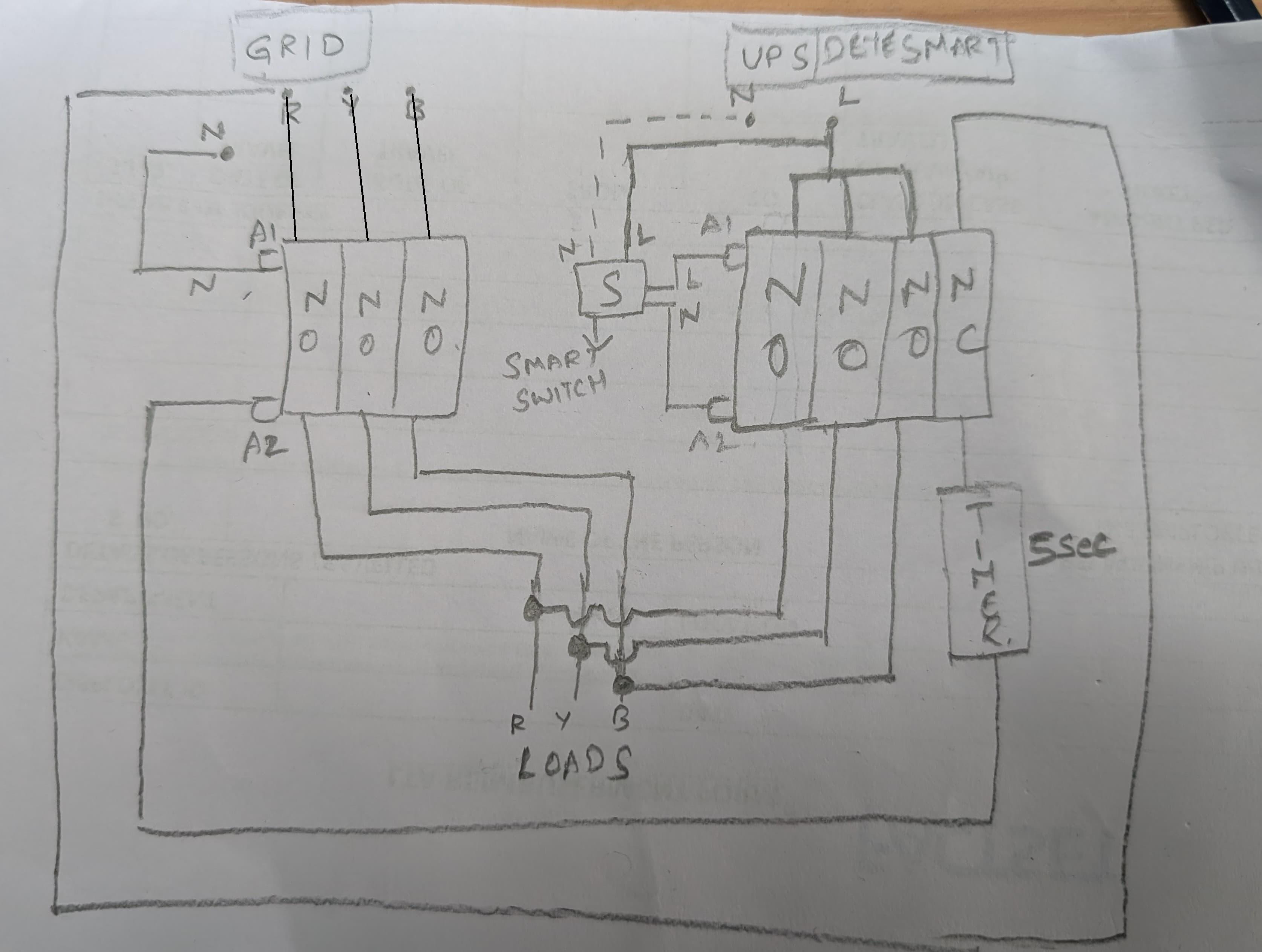
Not sure if i followed what you meant. There are no MCB's in the circuit, they are both contactors. 1 is a 3 pole 3NO contactor and the other is a 4 pole 3NO1NC contactor.
-
Thanks, Did a rough diagram of my simplest plan. need an extra pair of eyes to point out if i am doign something wrong. when drawing this up, i realized i made a mistake in my original plan where i was planning to use 1NO 1NC for the right side contactor. please let me know if you see any other issues like that. Some notes: 1. my Discom connection is 3 phase but i don't have any 3 phase loads. loads are just distributed across each phase. 2. My deye Solar inverter smart Loads output is single phase, so in my current manual changeover setup when i switch between grid and solar inverter, i feed the single phase of my deye inverter to all 3 phases of load. Now, To be able to make this changeover remotely. I plan to use the following hardware. 1. Contactor 3 pole - 3 NO 2. Contactor 4 pole - 3NO, 1NC 3. timer 4. Sonoff mini smart switch (tasmotized) During normal operation, the Left side contactor (3NO)'s coil will be powered through one of the grid phases but to achieve interlock with the solar inverter output, its coil input will be wired via the NC contact of the 2nd contactor. This will ensure that the main contactor will never be powered when the inverter contactor is ON. When there is a power cut, both contactors will be Off by default and the house will have no power (except critical loads that are wired separately and connected to critical loads output of inverter). However, i will have the option to turn on the Sonoff Smart switch 'S' from home assistant etc to energise the coil of the 2nd contactor which will power all 3 phases of the house via the single phase output of the Deye solar inverter. The house will remain powered via the inverter even when the Grid/utility power is back online and that is fine by me. When i need to switch back to utility power and offload my inverter, I can manually via my phone turn off the smart switch and this will cause 2nd contactor to deenergized. The NC contact on the 2nd contactor will complete the circuit for the main contactor coil to be energized after a delay of 5 sec which i will set on the timer device since i dont want/need the power switching to happen instantanously. Note: 1. My solar inverter is rated for 6kw and the house always remains under 4 kw typically unless my EV is charging which only i operate, so there is almost no chance of overloading the inverter and tripping it. 2.ignore neutrals missing in the diagram, they are common between Grid circuit and Deye inverter circuit and that works just fine in the current state where i have a manual changeover.

-
I wanted more manual control than the ATS automatically switching to inverter power when the grid is out. My inverter has a critical load output and a smart load output. The critical loads are always connected to the critical load output of the inverter and when there is a power cut the inverter takes over. The smart load output is used to power the entire house manually if the power is out when solar can generate during the day. I need this to be manual because, i can make sure all Heavy loads like geysers and inductions are not used during this time. I current have a manual changeover to do this switch but looking at options to be able to switch this over remotely and also have a interlock. Also, i don't want the switchover from grid to Inverter or wise versa instantaneously (Is this even safe for devices, might be since that is what the ATS is doing?), so i plan to use a timer when switching back from inverter power to Grid power
-
You just need this and a Rj45 cable. Cut one end of the RJ45 cable and screw in pin 7, pin 8 (generally White brown, brown on a straight patch cord) to this converter A and B ports respectively. https://robu.in/product/usb-rs485-converter-adapter-support-win7-xp-vista-linux-mac-os/
-
@junkesAny luck or did you give up? My battery has the exact same 1.5 version BMS and i can't get it working with the software or with my deye inverter. I have been scouring the internet and see SDA10-48100 batteries (mostly sold in aus and SA) have a similar bms.
-
Looks like this software is specific to the ND574 variant BMS you have. I tried the software to communicate with this board and no luck. Anyone knows where to find manuals for Shinwa BMS ? I have this board in my battery and can't get it to communicate with the Deye as well.