


SolarConvert
Members
-
Joined
-
Last visited
-
-
-
-
You'd need a changeover switch for the aux port for the same reason that you have a changeover switch for the essentials - so that you do not need to rewire things if you need to do repairs on the inverter. If you need to take off the inverter, both the essentials changeover and the aux changeover would be on the Eskom position side. Furthermore, I wanted to treat my oven/stove as non-essentials most of the time and only in load shedding situations where there was sufficient battery and/or solar would I treat them on an equal footing as essentials and they would start contributing to my essentials load, i.e. when the aux changeover switch is on the inverter position. Now it can be argued that if you do have an aux changeover switch, why not leave it in the inverter position permanently? After all, there is a setting on the inverter that allows you to power the aux load permanently if there is grid power, ignoring battery/solar minimum aux settings. My response to that would be that I was not sure whether the aux load, if permanently running even when there is grid power, would contribute to the load that goes through the inverter or not. Normally non-essentials do not go through the inverter and therefore do not place the inverter under load or count towards any maximum - the non-essentials load is a passthrough. I am not sure whether the same can be said for the aux load when there is grid power. If the aux load does place the inverter under load when there is grid power, then I would be unnecessarily potentially shortening the lifespan of the inverter. Because of this uncertainty and mainly for the reason at the beginning of my post, I feel the aux changeover switch is a must.
-
I didn’t want to open the inverter, DB board or trunking… Here is a 4.5 hour load shedding session today from 08:00 until 12:30. Actually grid power didn’t come on until after 13:00, so it was out for longer than what it was meant to be out for. You can see the cooking happening on aux power between 10:00 and 11::00 in the middle of load shedding, while the rest of the time the battery was being charged from PV. At 12:00 the battery was fully charged, so the PV power went to waste.

-
-
I went ahead and did this two months ago: Hooked up stove and oven (they didn’t have separate circuit breakers) to the aux port of my Deye, behind a changeover switch. So when there is no load shedding, the stove and oven are non-essentials, but if there is load shedding the changeover switch is flipped and they become aux loads and they can work from solar + battery. What a massive difference. This has enhanced the relationship with the wife.
-
-
I have one of those locally manufactured Opensprinkler boards available for sale if you are looking for one (not Zigbee). I bought two a long time ago and the second ended up never getting used. PM me if interested. Edit: It was sold.
-
I had some queries on how I send the data to the inverter via the CAN port, so I thought I'd share it here. Firstly you'd obviously need to connect your CAN HAT or module to the inverter and PI with the correct pins which are available in earlier posts. Then, there were 3 PDF documents which contained some very useful information on the CAN frames that I needed to map the BMS data to. These I posted in one of my previous posts here: As for the PI configuration, you'd need to enable the CAN module as per your HAT or adapter's instructions. In my case I consulted this manual for my Waveshare RS485 CAN HAT. Once the module is enabled, you'd bring up the interface, something like the following; sudo ip link set can0 up type can bitrate 500000 I then use python-can in my Python script to send things to the CAN module. Here is an excerpt from the script which shows how to send the CAN frames: import logging import struct from time import sleep import can import battery_tian_power import serial logger = logging.getLogger(__name__) logging.basicConfig( format="%(asctime)s %(levelname)-7s %(message)s", level=logging.INFO ) with serial.Serial( "/dev/ttyS0", baudrate=9600, parity=serial.PARITY_NONE, stopbits=serial.STOPBITS_ONE, bytesize=serial.EIGHTBITS, timeout=1, ) as ser, can.interface.Bus(channel="can0", bustype="socketcan") as bus: logger.info("Reading protection parameters") bms = battery_tian_power.TianPowerBattery() protection_params = bms.read_protection_params(ser, 1) logger.info("Reading battery info") while True: info = bms.read_info(ser, 1) charge_voltage = int(protection_params.pack_ov_start * 10) discharge_voltage = int(protection_params.pack_uv_start * 10) charge_current_limit = int(protection_params.charge_oc_start * 10) discharge_current_limit = int(protection_params.discharge_oc_start * 10) data = struct.pack( "<HhhH", charge_voltage, charge_current_limit, discharge_current_limit, discharge_voltage, ) msg = can.Message(arbitration_id=0x351, data=data, is_extended_id=False) bus.send(msg) soc = int(info.soc) soc_hires = int(info.soc * 100) soh = int(info.soh) data = struct.pack("<HHH", soc, soh, soc_hires) msg = can.Message(arbitration_id=0x355, data=data, is_extended_id=False) bus.send(msg) voltage = int(info.voltage * 100) total_current = int(info.current * 10) avg_cell_temperature = info.temperatures[-1] * 10 data = struct.pack("<hhh", voltage, total_current, avg_cell_temperature) msg = can.Message(arbitration_id=0x356, data=data, is_extended_id=False) bus.send(msg) protection1 = 0 # mapping ommitted in this example protection2 = 0 # mapping ommitted in this example alarm1 = 0 # mapping ommitted in this example alarm2 = 0 # mapping ommitted in this example module_count = 1 data = struct.pack( "<bbbbbbbb", protection1, protection2, alarm1, alarm2, module_count, ord("P"), # careful that we don't act like a Pylon BMS here, maybe omit sending this ord("N"), # careful that we don't act like a Pylon BMS here, maybe omit sending this 0, ) msg = can.Message(arbitration_id=0x359, data=data, is_extended_id=False) bus.send(msg) # data = "PYLON".encode("ascii") # the Deye inverter does behave differently when the manufacturer is PYLON vs something else data = "Narada".encode("ascii") msg = can.Message(arbitration_id=0x35E, data=data, is_extended_id=False) bus.send(msg) sleep(1) I've enabled the above interface command and Python script to run on startup on the PI. Also a neat feature of the PI is to enable the watchdog to reboot the PI in case anything goes wrong as outlined here. There are obviously many ways to do the above things, so what I did is merely one of the ways. I hope the above is useful to anyone who might be attempting the same thing.
-
-
Try this software instead for LM-M01A.
-
I have managed to decode the response and have amended my first post to include BMS protection data.
-
So to get the current in amps, you need the following formula Current = (30000 - value_of_item_2) / 100 30000 is a static value from which you need to subtract the value of item 2 returned by the BMS. I assume that Tian Power did this so that only unsigned values are returned by the BMS when queried, therefore some items not only have a scaling factor but also an offset to subtract from, if that makes sense? I'll update the first post with the latest info I have - there is a lot of new info.
-
-
So the script would still read both batteries (or more if there were) but would combine the the values from the batteries. For example, it would report the average voltage across them and it would sum up the current. But comms would be through the master battery (the one currently connected to the inverter). The caveat I mentioned in my previous post was that currently your inverter knows about both batteries and combines their values on the main LiBMS screen, whereas with the script it would no longer know about them and the combining would be done on the PI. I just want to send you a script to run to ensure that the proper values are read from the batteries. If it works, then yes. But I first need to decode the Shinwa protocol, just like the Tian Power one.
-
-
Ok after a lot of searching and asking for some expert advice, I believe this is as good as the RS485 to CAN translation is going to get - CAN bus works in such a way that the inverter only ever sees one battery, even if that is made up of multiple modules. This would then be the tradeoff if switching from RS485 to CAN using a PI as the translator - you would not be able to see the individual module details anymore on the inverter. To me this is perfectly fine because I never had BMS comms via the RS485 port to begin with, but for others this may not be and you may prefer to stick with the inverter RS485 port for BMS comms rather than monitoring the inverter. @Jay-Dee your thoughts? I would still like to tweak the script to use 0x35A instead of 0x359 for the alarm/warning bits.
-
-
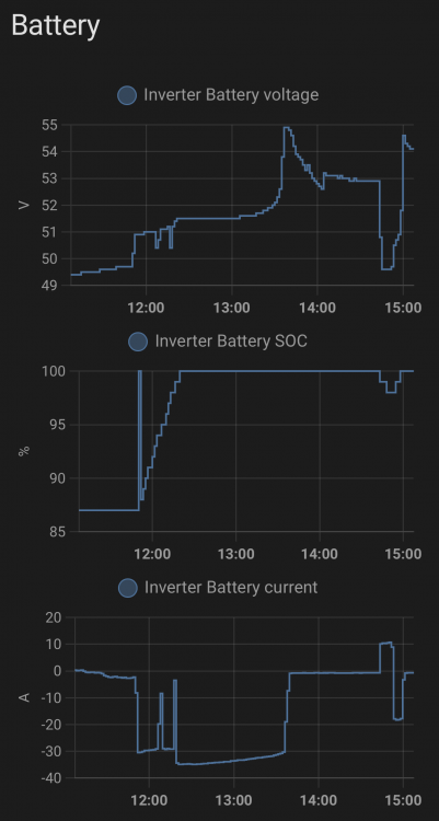
So I didn't make much progress in the meantime, but let me post some more detail as promised. Firstly, the Tian Power output that I was trying to understand: 7e01439400020e10010203e802020dac03020af0040203e805020c1c0602154a070203e8080214c8090211940a0203e80b0213880c021f400d0203e80e021b580f021f40100203e811021b581202006913020fa01402005f1502003216020fa01702003c1802006919020fa01a02005f1b0200321c020fa01d02003c1e02008c1f020fa0200200872102000a2202000f23020320240201f4de0d Means the following: { "cell_ov_start": 3.6, "cell_ov_delay": 1000, "cell_ov_stop": 3.5, "cell_uv_start": 2.8, "cell_uv_delay": 1000, "cell_uv_stop": 3.1, "pack_ov_start": 54.5, "pack_ov_delay": 1000, "pack_ov_stop": 53.2, "pack_uv_start": 45.0, "pack_uv_delay": 1000, "pack_uv_stop": 50.0, "charge_oc_start": 80.0, "charge_oc_delay": 1000, "charge_oc_stop": 70.0, "discharge_oc_start": 80.0, "discharge_oc_delay": 1000, "discharge_oc_stop": 70.0, "cell_ot_start": 55, "cell_ot_delay": 4000, "cell_ot_stop": 45, "cell_ut_start": 0, "cell_ut_delay": 4000, "cell_ut_stop": 10, "env_ot_start": 55, "env_ot_delay": 4000, "env_ot_stop": 45, "env_ut_start": 0, "env_ut_delay": 4000, "env_ut_stop": 10, "mos_ot_start": 90, "mos_ot_delay": 4000, "mos_ot_stop": 85, "capacity_low_start": 10, "capacity_low_stop": 15, "volt_diff_start": 800, "volt_diff_stop": 500 } These are the protection parameters that the BMS returns for command 7e 01 43 00 fe 0d. This allowed me to get the charge and discharge current limits (80A for both) as well as the charge and discharge voltages from the BMS and send them to the inverter. I compared all of the values to my attempt of using Lithium mode 7 a few months back and the results were very similar. Here is a photo from a few months back: If you recall, Lithium mode 7, which is meant for Revov batteries, didn't work for me at the time because not all of the values interpreted from the BMS by the inverter were correct, for example, the mean temp was wrong and I almost immediately got an error condition on the inverter, likely because it interpreted the alarm bits incorrectly. Nevertheless, the above photo at least gave me a point of comparison and I felt more comfortable with the charging/discharging voltages and currents that i am sending to the inverter now via the CAN port. Here is what the screen looks like with my current script running on my PI which queries the BMS via the battery RS485 port and sends the results to the CAN port of the inverter. The script has been running well, I made it start automatically when the PI is rebooted. For me, this is a much needed upgrade since I never had BMS comms working before. However, I cannot figure out in what format I should send the PACK information to the inverter, so you will see above that the Sum Data and Details Data buttons are missing, because the inverter does not know about the individual batteries, just the battery "system" as a whole. This is not a problem for me since I only have one battery anyway, but for those that would like to use this script, you would lose the ability to see the details of the individual battery packs, unless there is some way I can send the pack info to the inverter too. I cannot find any documentation or examples online where pack info is sent on the CAN bus. This is very interesting and I actually didn't know what the derating file was for, but now that you explained it, it makes a lot of sense. I ran my script without any derating functionality and the inverter appeared to do the right thing as per the graph below - note that at the time I took the screenshot I had not even implemented any alarm bits either. The charge current did decrease as soon as the voltage went past 54.5V. I am actually thinking of using pack_ov_stop instead of pack_ov_start for the voltage limit because pack_ov_start means that 54.5V is already "over voltage" so using the lower value (53.2V) should prevent the pack_ov_start value from being reached. As an aside, if you're wondering why the spike to 100% SOC just before 12:00 and then back down - it is because I switched the inverter from Lithium mode 0 back to Battery % mode (so no more BMS comms via the PI) and the inverter thought that the battery SOC was 100%, then I quickly switched back to Lithium mode. That being said, do you think derating is needed? On the one hand I think that the derating feature is great since it does a similar thing as the expensive + intelligent BMSes, but on the other hand, does one actually need to worry about derating whether using RS485 or CAN for BMS comms? I am happy to take a stab at getting the Shinwa protocol to work, I'd probably send you a script to test out on the PI to see if the output values make sense. However, please note above that i cannot get the pack information to work at this stage, so you would lose the ability to monitor individual batteries. That may be a deal breaker for you. Regarding the CAN bus module, I use this the Waveshare RS485 CAN HAT which does both RS486 and CAN, plus it connects directly to the ports, no need for USB. There are many other options for CAN interfaces though, for example on this page. I am going to keep searching for how to get pack information to the inverter via CAN. Surely it must have been done before. I cannot imagine that if you use the CAN port directly on the inverter with a supported BMS that you cannot monitor the individual batteries irrespective of the BMS manufacturer?


-
-
-
Ok progress made on this. I now know what each of the numbered items mean above and I know the meaning of the alarm bits on the BMS side. What is left to do is to map the BMS alarm bits to CAN 0x359, as well as to get pack info to the inverter - currently the inverter does not allow me to go into the details of each individual battery (even though I have just one), so it's just the summary screen that is available as per my previous screenshot (though the values are now all real values from the BMS). Will post more info tonight.
-
Thanks for the link @JustinSchoeman. I managed to get CAN IDs 0x351, 0x355 and 0x356, but 0x359 is the tricky one which I don't find examples of, especially when the alarm/warning bits are set. By far the best set of docs for the CAN IDs I have found is the SMA CAN protocol one SMA CAN protocol.pdf, but I attach the Sunsynk Sunsynk Battery Compatibility v4.pdf and Pylontech CAN-Bus-protocol-PYLON-low-voltage-V1.2-20180408.pdf docs too. Whilst 0x351, 0x355 and 0x356 are a huge upgrade for me since I never had BMS comms, I do think that 0x359 is very important because the inverter must know about any fault conditions of the battery. Those who already had proper BMS comms working via RS485 and choose to go with this RS485/CAN translation route (like @Jay-Dee ) should get no less than what they had before when there was direct BMS comms between the inverter and the battery. Pages 3 of the Pylon CAN protocol doc is what I'm going to tackle next. The hard part for me is figuring out the Tian Power BMS protocol and mapping it to CAN ID 0x359, including the alarm / warning bits, as well as cherry picking the correct values from an unknown dictionary of data. For example, the following response from my BMS contains a lot of useful information, but deciphering it is hard: 7e01439400020e10010203e802020dac03020af0040203e805020c1c0602154a070203e8080214c8090211940a0203e80b0213880c021f400d0203e80e021b580f021f40100203e811021b581202006913020fa01402005f1502003216020fa01702003c1802006919020fa01a02005f1b0200321c020fa01d02003c1e02008c1f020fa0200200872102000a2202000f23020320240201f4de0d Here it is translated: {0: (3600,), 1: (1000,), 2: (3500,), 3: (2800,), 4: (1000,), 5: (3100,), 6: (5450,), 7: (1000,), 8: (5320,), 9: (4500,), 10: (1000,), 11: (5000,), 12: (8000,), 13: (1000,), 14: (7000,), 15: (8000,), 16: (1000,), 17: (7000,), 18: (105,), 19: (4000,), 20: (95,), 21: (50,), 22: (4000,), 23: (60,), 24: (105,), 25: (4000,), 26: (95,), 27: (50,), 28: (4000,), 29: (60,), 30: (140,), 31: (4000,), 32: (135,), 33: (10,), 34: (15,), 35: (800,), 36: (500,)} I assume item 6 is charge voltage (54.5V), which plugs into CAN ID 0x351, but I'm not quite sure which one is max charge and discharge current, so I have them hard-coded for now. I don't see why not. If the Shinwa BMS software works for you, it should be fairly easy to get the required protocol. But it will take some time to get this stable enough for you to be able to run it and forget that it's running. I also think that if SolarAssistant supports this down the line, it would be better to use that since it is a supported product, but until they have this feature, an interim solution would work.
-
I have some good progress with the RS485/CAN translation. The Battery Voltage, Current and SOC are read from the BMS via RS485 and sent to the inverter via the CAN port every second. The rest, such as Battery Temp, Alarms, Charge Voltage and Charge/Discharge limits are currently hard-coded until I get them mapped from the BMS info. No pack information yet either. Documentation and examples are very scarce, which adds to the difficulty.

-
I worried about this with the splitter option. Each MODBUS request includes a transaction ID and the MODBUS response needs to include the same transaction ID. In theory, even if there are two senders (the PI and the Data Logger), if the inverter responds to each of them and includes their respective transaction IDs (which it must according to the spec), this should all work provided that each original sender ignores responses that are not destined for it (and of course the transaction IDs are different for each sender, which should hopefully be the case with randomly generated transaction IDs). That is the theory. In practice, however, I see two possible issues: The senders may not check a response’s transaction ID matches their own request’s transaction ID, i.e. whether a response is destined for them. Blindly accepting/processing it would cause the processing of a completely incorrect response. I have found this to be true in some Python MODBUS libraries, but cannot comment on how the Data Logger would process the responses, or on which library is used by Solar Assistant / other monitoring tools. An example of this would be the Data Logger requesting certain info from the inverter and the response it receives is something that the PI asked for, or visa-versa, simply due to timing. I am not even sure what the splitter does with the responses from the inverter - do both senders get a copy of the response? I’d assume so and if that were true, then point 1 above is still a problem. If not, then that is even worse where responses may get lost due to splitting / multiplexing. For example, the PI reads the response that the Data Logger is waiting for and the Data Logger never gets it because it was consumed by the PI. The issues you are experiencing may be due to the above, though that is speculation on my part. Even so, I’d be curious to find out the answers to the above even if it were purely academic.


