GerhardZA
Members
-
Joined
-
Last visited
Everything posted by GerhardZA
-
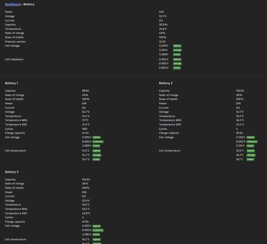
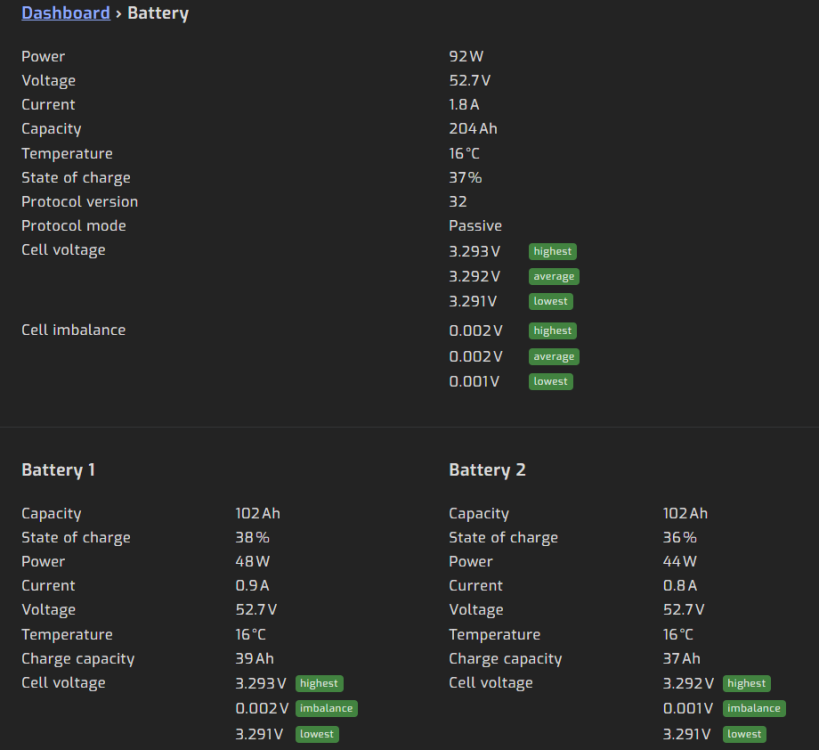
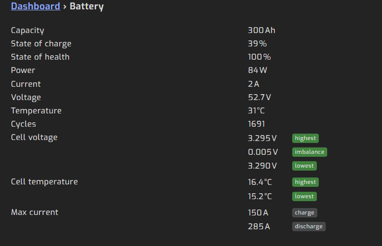
Good day, I need some assistance with configuring communication between my inverter, batteries, and Solar Assistant. My setup consists of: LuxPower SNA 5000 with the latest firmware 3 × Shoto SDC10-Box5 batteries Solar Assistant running on a Raspberry Pi The battery bank is connected to the inverter via CAN, and the battery is connected to Solar Assistant using a LAN-to-USB cable connected to the Pi. Initially, everything was working correctly with a single battery: Solar Assistant was configured for USB Serial RS232/485 Inverter setting Option 3 was set to Lithium Manufacturer was set to 2 All DIP switches were OFF With this setup, both the inverter and Solar Assistant could read the battery correctly with full details. The issue started after I added two additional Shoto SDC10-Box5 batteries. We first connected the batteries with LAN cables according to the manufacturer instructions: Battery 1 Port A → Battery 2 Port B etc. I have played around with the order port A or B and it does not seem to make a difference DIP switches configured according to the Shoto manual (see below) Solar Assistant connected to Battery 1 Port B, as before adding the extra batterry's SHOTO DIP switch configuration: Dip SHOTO 1 2 3 4 5 6 7 8 Battery 1 x Battery 2 x Battery 3 x With this configuration: The inverter reads the battery bank correctly and operates normally However, Solar Assistant only detects two batteries This causes inaccurate reporting. For example: The inverter may show a 1 kW load But the batteries only show around 666 W discharge because Solar Assistant is not detecting the third battery Option 2 When I change the DIP switches according to the Solar Assistant instructions, Solar Assistant detects all three batteries correctly, BUT the inverter can no longer communicate with the battery bank over CAN. The inverter then switches to grid mode and shows Error 00. Solar Assistant DIP switch configuration: Dip SA 1 2 3 4 5 6 7 8 Battery 1 x Battery 2 x Battery 3 x x A third option I tried was: Keeping the DIP switches configured according to the SHOTO instructions Setting Solar Assistant to read battery information from the inverter instead of directly from the batteries This setup seems to work properly: The inverter operates normally Solar Assistant reports the total battery bank correctly I had to set inverter Option 3 to Lithium and Manufacturer to 6 for the inverter to detect the bank as 300 Ah The only downside is that Solar Assistant now only shows the battery bank as a single combined battery and not the three individual packs separately. Am I missing something in the configuration, or is it normal that I cannot monitor all three packs individually while still maintaining proper CAN communication with the inverter? Any advice would be greatly appreciated.

-
Thank you for this. I miss read that boost / float charge voltage... 😞 I have these settings configured now. Will monitor during loadshedding and maybe adjust a little bit if needed. Thank you for the assistance

-
Good day everyone, I purchased a Shoto SDC10-Box 5 (5.12kWH) 16 Cell battery and need some assistance on the battery settings to use. I have a Kodak OG548 Inverter, I have Solar Assistant and waiting for my cable to arrive. So my question is what settings should I use without the cable and then which setting should I use with the cable. I require assistance on the following: Shutdown battery voltage Battery float charge voltage Battery absorption charge voltage It is probably too low, but I was conservative as I do not want to damage the battery. I currently have it se to: 44.0v 53.4v 54.0v I was thinking to set it to the below settings, but just wanted someone to confirm if its correct. 42.0v 56.0v 57.6v Below is info about the battery: General Data • Model: 51.2-100 16Cell • Nominal Capacity (kWh): 5.12 • Rated capacity: 100AH • Operating voltage range: 42V to 57.6V • Boost Charge / Float Charge Voltage: 57.6V / 54V • Depth of Charge: 90% • Usable Capacity (kWh): 4.6 • Charge Voltage: 57.6V • Discharge Voltage: 48V • Nominal Voltage: 51.2V • Maximum Parallel Units: 16 • Communication Port: RS485 & CANBUS • Cycle Life: ≥5000 @ 25°C • Humidity: 5%-95% • Altitude: ≤ 4000m • Certificate: TUV(IEC 62619)/CE-EMC/UN38.3 • Installation Method: Rack Mount / Wall Mount • Terminal Stud: M8 Charge / Discharge Current • Max 100A (1C) • Recommended 50A (0.5C)
-
Ok, I got it sorted. I disconnected the battery and PV. Switched off the grid power, waited 10 seconds and switched the grid back on. Now here is where it gets tricky... I had to time when I clicked update on the software perfectly, its about 4 seconds after I switch on the grid. Just before the inverter starts making clicking noises. I flashed it with the 102.73 display firmware and everything is working now 🙂 Thank you for the assistance and guidance. I have another question, but will start a new thread... 🙂
-
Hi there thanks for the quick reply I purchased the inverter in July. It still seems to be working, but don't get any output from solar assistant or watch power. The link to the files can be found in a document I found through Google. I will try to attach it. https://365segen.sharepoint.com/:f:/s/SegenFirmwareControlCentre/Eo8IcyCk4eBLiinpkWIjXlABPIlPjzaRe6wjHV6NC_quuQ?e=jkefzT What other info can I provide you to help find a solution? Application Note – KODAK OG RANGE FIRMWARE UPDATE PROCEDURE .4 updated (4).pdf

-
I need assistance please. I upgraded the CPU and MCU firmware of my inverter with the files in the link below. The CPU went fine, but the MCU has a problem. It completed successfully, but when it auto restarted, it did the normal countdown from 6 but it's stuck at 2 now. I have restarted everything but it does the same. Please don't tell me I bricked it... 😞 https://365segen.sharepoint.com/sites/SegenFirmwareControlCentre/Shared Documents/Forms/AllItems.aspx?ga=1&id=%2Fsites%2FSegenFirmwareControlCentre%2FShared Documents%2FKODAK%2FOG5.48&viewid=67638a2a-c217-436b-9e6e-fc0ae45f8824 Any help or advice will be appreciated Regards Gerhard
-
Mine does the same. And can't RMA it because I work wrom home and with loadshedding I need it 24/7
-
Mine does the same. I have two in different sites, but the one is making this whiney sound. Problem is I can't RMA it because I work from home and loadshedding means I need it 24/7
-
Just for anyone reading this in the future. I got a qualified electrician to do the connection. 🙂
-
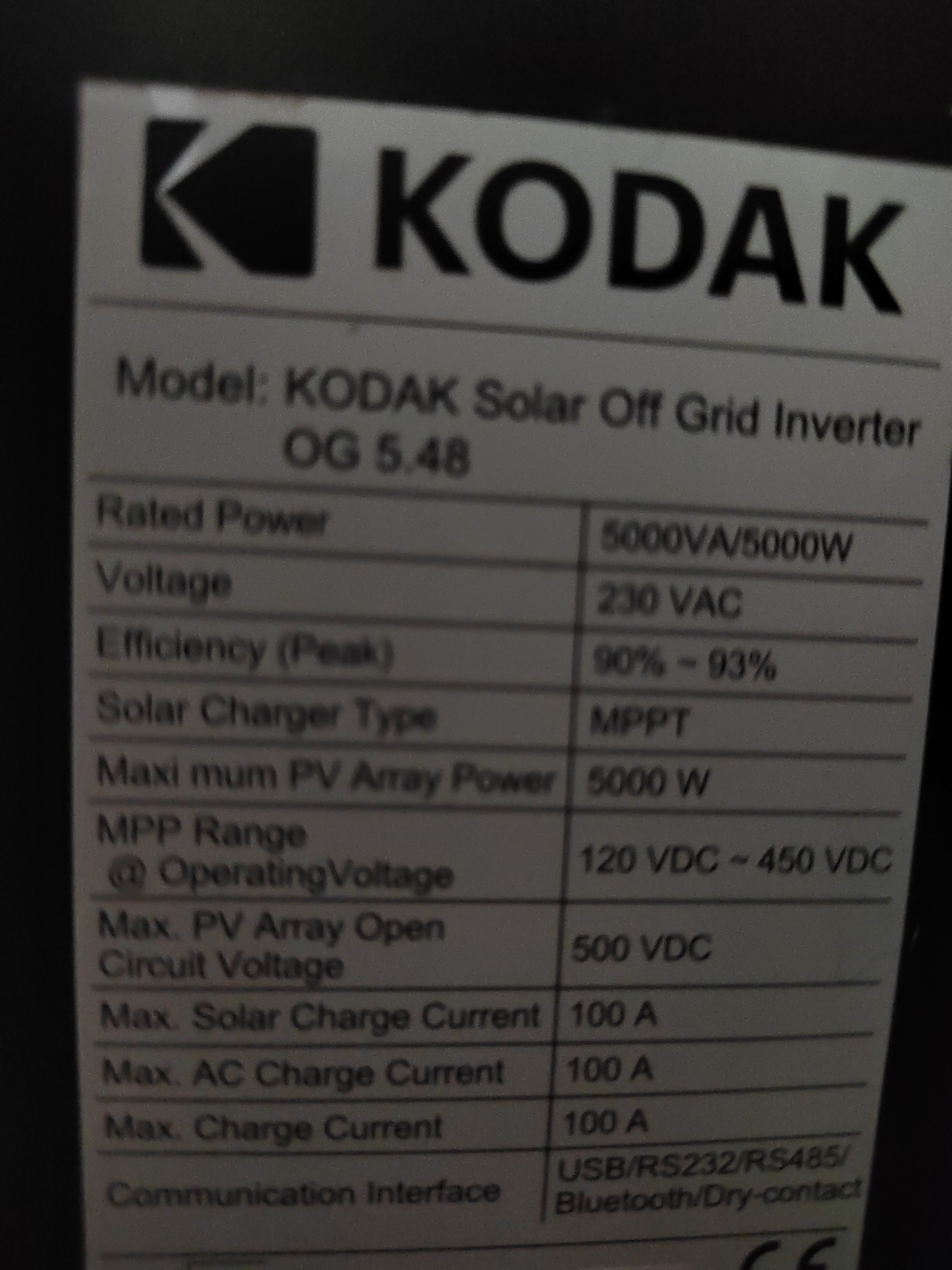
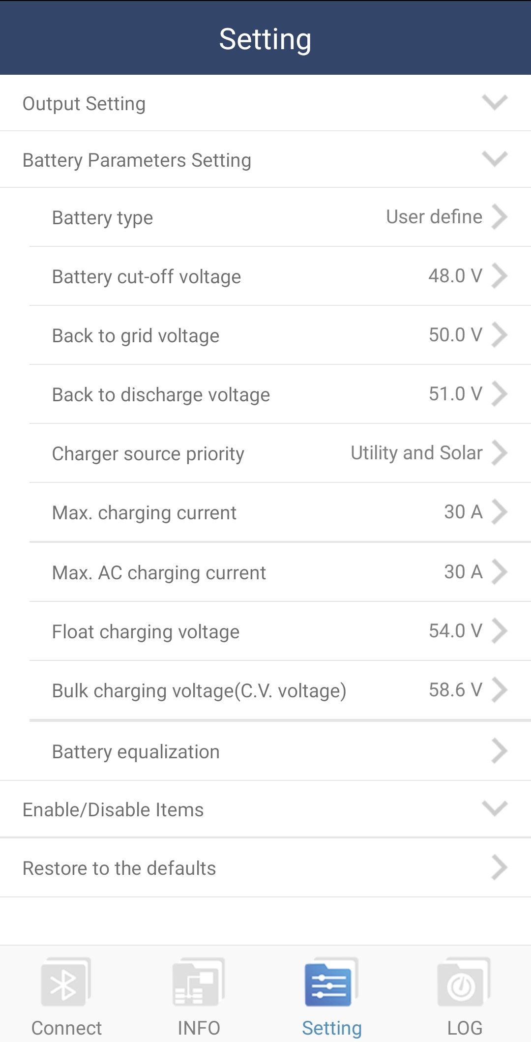
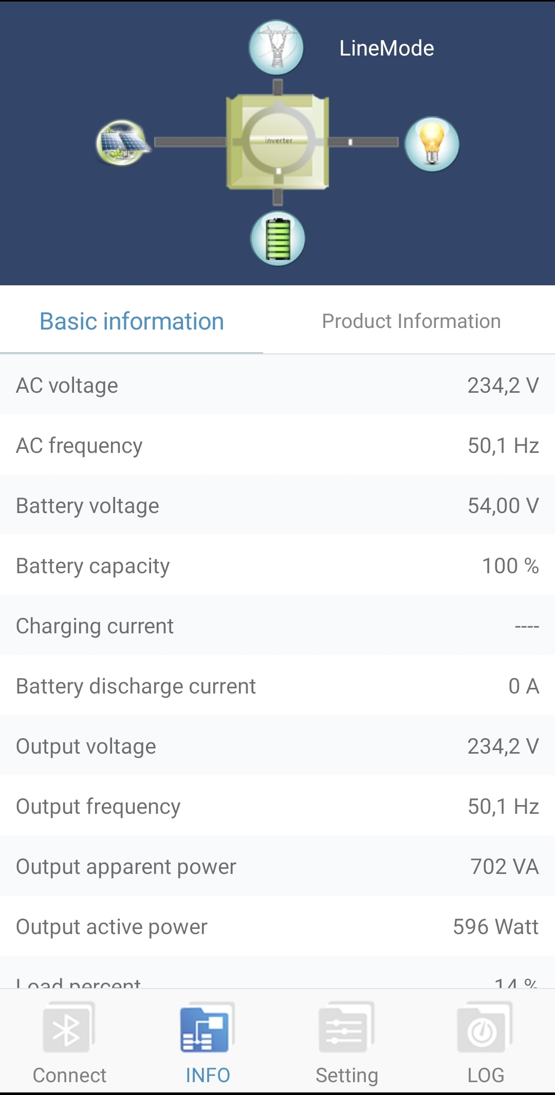
Good day, I have a Kodak OG 5.48 inverter and 8x CSB HRL 12330 batteries that is connected to utility power (no PV at this stage). It is connected to run the entire house (except geyser) and during load shedding we make sure not to turn on anything that generates heat (stove, kettle, tumble dryer, etc...) I just want to make sure that the settings are correct. The reason I'm asking is that the fans on the inverter runs the whole time, even on a constant load of 400w. And I'm concerned that its using batteries or overcharging them. I have seen conflicting settings and I have chosen what seems to be the middle ground... 01 - Output Source Priority: USB 02 - Maximum Charging Current: 30A 05 - Battery Type: USE 26 - Bulk Charging(C.V) Voltage : 48V 27 - Floating Charging Voltage: 58.6V 29 - Low DC cut-off Voltage: 48V I have attached a screenshot of additional parameters of the PowerWatch mobile app and of the label on the inverter. Any help and guidance will be highly appreciated. Regards Gerhard CSB-HRL-12330_datasheet.pdf


-
Good day, I'm new to the whole inverter, batteries and panels game and require some info on setting up my system. I have a Kodak OG 5.48 inverter and 8x CSB HRL 12330 batteries that I would like to connect to my home power. I will add panels at a later stage when I have saved up enough money... I have done alot of research into the topic and its been quite overwhelming. I have an idea of what accessories I require and have already purchased some of them. So, what I'm after is how to connect everything, if anyone can provide me with basic schematics it will be highly appreciated. I got a drawing from a solar technician, but there is a lot I'm not sure of and that does not seem logic. The idea I have is as follow: Power from eksdom running from my current electrical box to a new one that will be close to the inverter. In this new electrical box there will be an isolator, earth leakage and a switchover. And here is where it gets weird... I want the power from eksdom to run into the input of the inverter via this new electrical box, then the output from the inverter must run to the new electrical box and then to the old one to connect to my plugs and lights. Only my geyser must run directly from eksdom (for now) This is alot of live, neutral and earth wires running in all directions... 😞 I do not have space at my current electrical box for everything so the inverter and new electrical box will be about 5m from the current electrical box. If there is anyone willing to assist or guide me in the correct direction with this project it will be highly appreciated Regards Gerhard