Wiebo
Members
-
Joined
-
Last visited
-
No, this doesn't use modbus. It only gets the BMS data from the battery via Pylontech protocol, and it puts the data in a table, and translates this table to the string to send every 5 seconds. Got not much time to work on it lately to combine it with the smartmeter, but i'll certainly finish it someday :) The smartmeter data is also filtered and the injection and extraction power is also put into the "^S026EMINFO" string and sent to the inverter every second, combined with the BMS string every 5 seconds.
-
 Wiebo reacted to a post in a topic:
Infinisolar / MPI 10K / Voltronic hybrid inverter and BMS communication with DIY battery
Wiebo reacted to a post in a topic:
Infinisolar / MPI 10K / Voltronic hybrid inverter and BMS communication with DIY battery
-
Wiebo reacted to a post in a topic:
Infinisolar / MPI 10K / Voltronic hybrid inverter and BMS communication with DIY battery
-
And the module is finished, programmed and tested. Next is a smartmeter to RS485 adapter to connect the smart meter to this module on the 2nd port and establish communication with bms and smart meter over a single serial port. Zero injection (nulleinspeisung) could also be performed with BMS communication on a single PCB.


-
 riogrande75 reacted to a post in a topic:
Infinisolar / MPI 10K / Voltronic hybrid inverter and BMS communication with DIY battery
riogrande75 reacted to a post in a topic:
Infinisolar / MPI 10K / Voltronic hybrid inverter and BMS communication with DIY battery
-
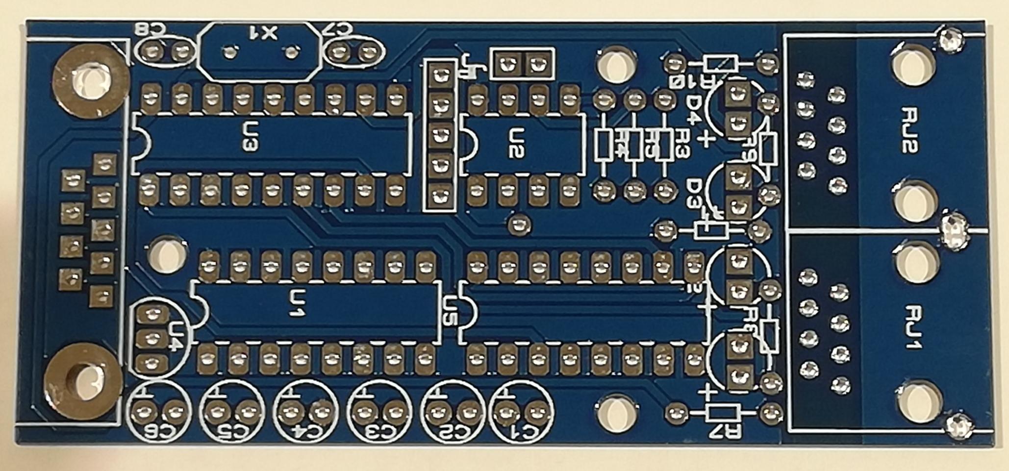
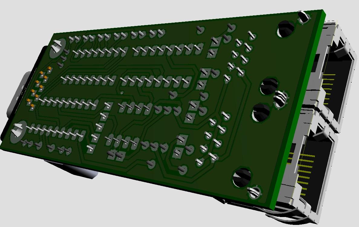
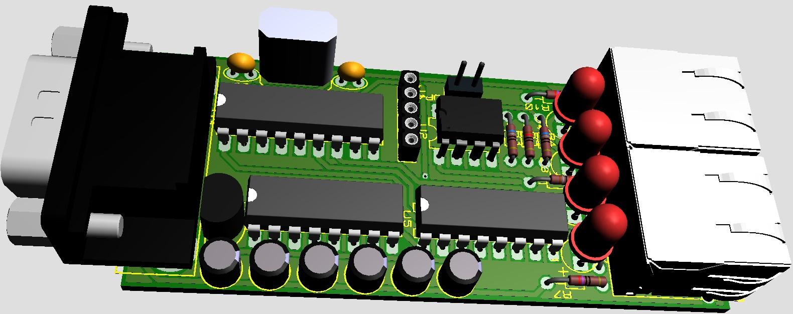
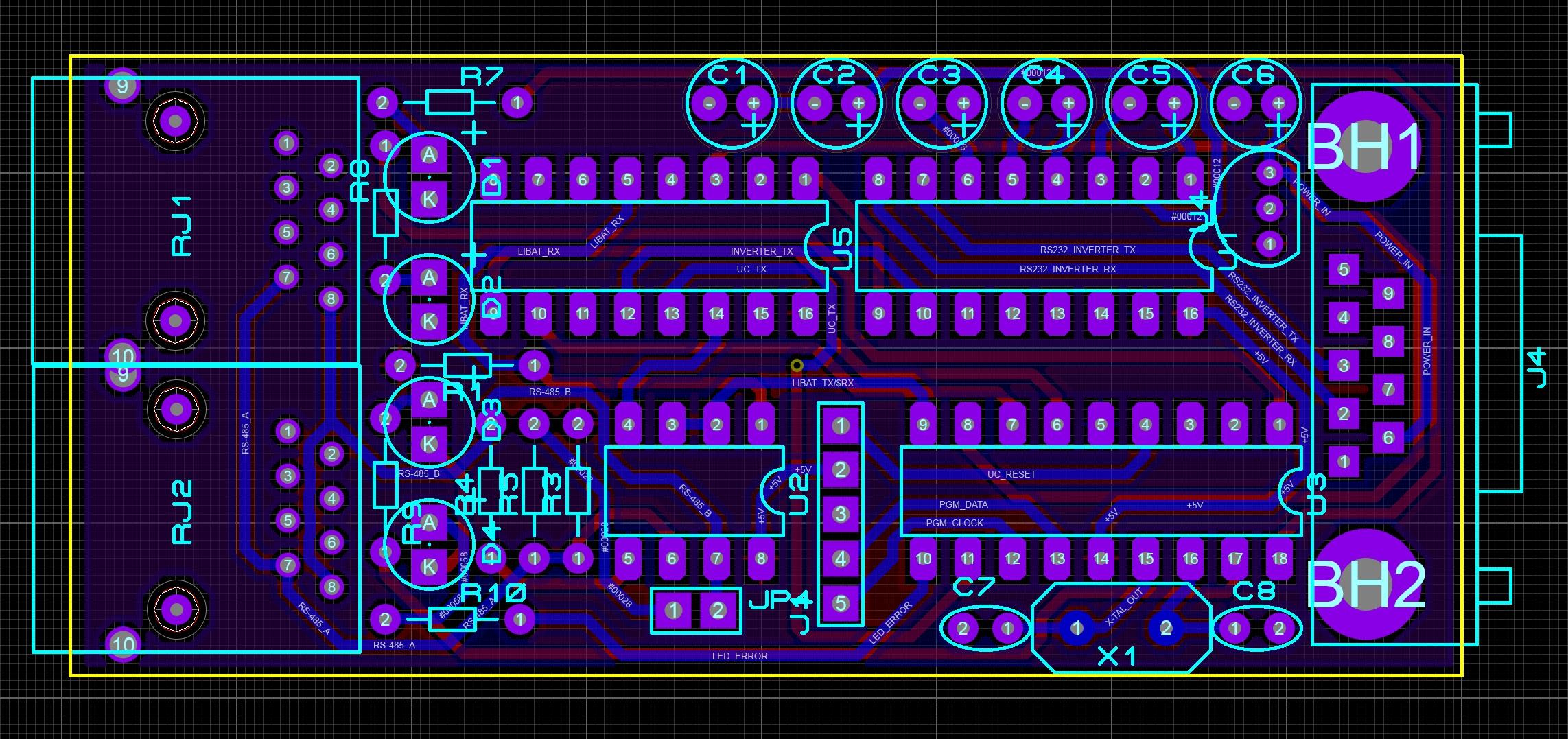
This is the design. Time to build it...


-
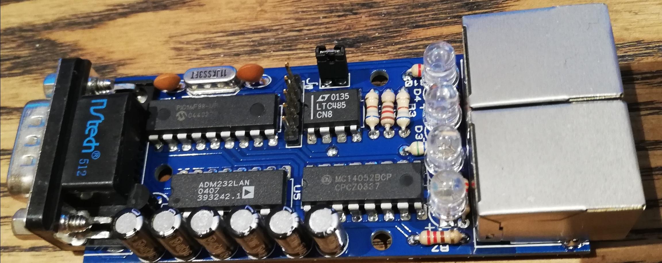
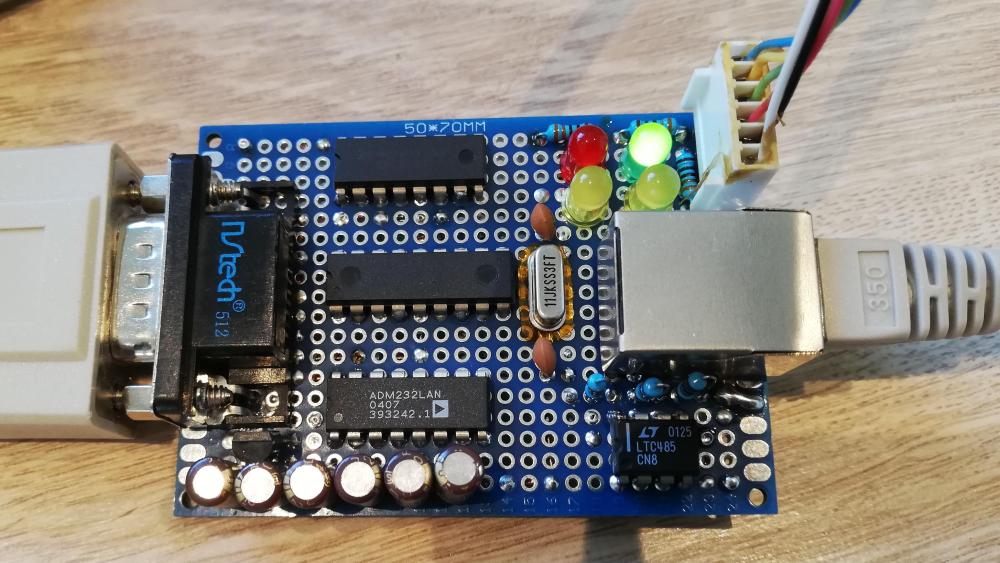
It is the PCB i posted the picture from. That was a PCB i quickly soldered together so i could start writing software for the PIC controller. The PCB contains a PIC16F88 from microchip, a MAX232 levelshifter for the serial port to the inverter, a MAX485 to drive the RS485 bus to the battery, and a CD4052 analog 4x2 multiplexer to switch toe PIC's hardware the serial port to the inverter ot the battery. It reads the battery data and puts the Pylontech ASCII data to HEX in the corresponding values in an array. When all data is gathered the string is prepared and the hex data translated to ASCII values. The portspeed is changed from 115200bps to 2400bps and the string is sent to the inverter. All of this is powered by the serial port DB-9 connector pin 6 of the IGRID TT 10kW inverter (Infinisolar) and works on itself, without adapter. The only thing i need to do is draw the final PCB and put some extra datavalidation in the code. Was thinking to put a second RJ-45 connector on the board to let the battery data being sniffed by a large battery indicator build with LED's to put on the wall in the livingroom. Any extra handy ideas are welcome Was also playing with the idea that i and someone else had to reduce the charge current gradually when SOC reaches almost 100%... It's an option. Also have some spare pins, maybe for jumpers to let's say, choose battery communication speed selection of 155200 bps or 9600 bps (Pylontech has both) But questions to you Rio, The charge/discharge value to the inverter that you get from the total battery current, is the '1' charge and '0' discharge? And the Charge Voltage and Float voltage, i keep them the same, bc the BMS lowers the value if float mode is activated. But did not test this yet.

-
Ok, got it! Thanks man! My module is running. No PC or external PSU needed 😛
-
Riogrande, How do you translate 0xFF8E in yellow to 11Amp and "Charge"?
-
Wiebo reacted to a post in a topic:
Infinisolar / MPI 10K / Voltronic hybrid inverter and BMS communication with DIY battery
-
Riogrande, how do you read those high currents from the BMS? I have a JK inverter BMS, configured as Pylontech, protocol v3.3 but struggeling to read the max charge and discharge currents. All goes well untill 68 Amps. Above that i get the strangest values... Have you seen this before? I sent this string: ~201246630000FDA8 + /0x0D and get the response, but the values of the current also starts to jump around above 68 Amps. I have to note that the ASCII values are minus 5%, the BMS does this and is normal behavior. The current seems to be in mA, 16 bits, so that's 65,635 Amp in the max current i can read. But i need to go to 200Amp. Is this even possible with Pylontech? Nevermind! I used a JK BMS and there's a bug in it, found it and reported it to JiKong.
-
-
Meanwhile got the whole thing running on a small PCB standard trough-hole PCB. Still wired bc my final PCB needs to be drawn first. It's based on a PIC16F88 and draws its power directly from the serial connector of the inverter. Just plug it in in the inverter, and the RS485 cable and it works. 4 LED's: - Green = Power (Power blinking = no BMS connected, constantly on = communication is OK) - Yellow 1 = Communication with BMS - Yellow 2 = Communication with Inverter - Red = Error Still bebugging tough. Some values need to be calculated but the main code works flawlessly. Does anybody know how you handle the warnings? My inverter does not respond on any inputs i tried
-
So Rio, to be brief... The only thing the BMS box does is sending the ^D054BMS(+BatteryData) string to the inverter at fixed intervals? In that case you actually don't need the Pylontech protocol if you translate directly from the JK BMS to Voltronic protocol. Is that correct? EDIT: Nevermind, already got it working thnx 2 U!
-
Thank you very much for that link Rio! Have the same inverter, the 3 phase 10kW version. Indeed, exists in also 15kW version and connected with JK BMS, so we're working at the same project
-
Did you log the datatraffic with a spy at the RS232 port of the inverter? Would be very interested. You could simulate the battery with Docklight. Maybe i can help