Volker
Members
-
Joined
-
Last visited
-
90V problem, firmware version V56.09

-
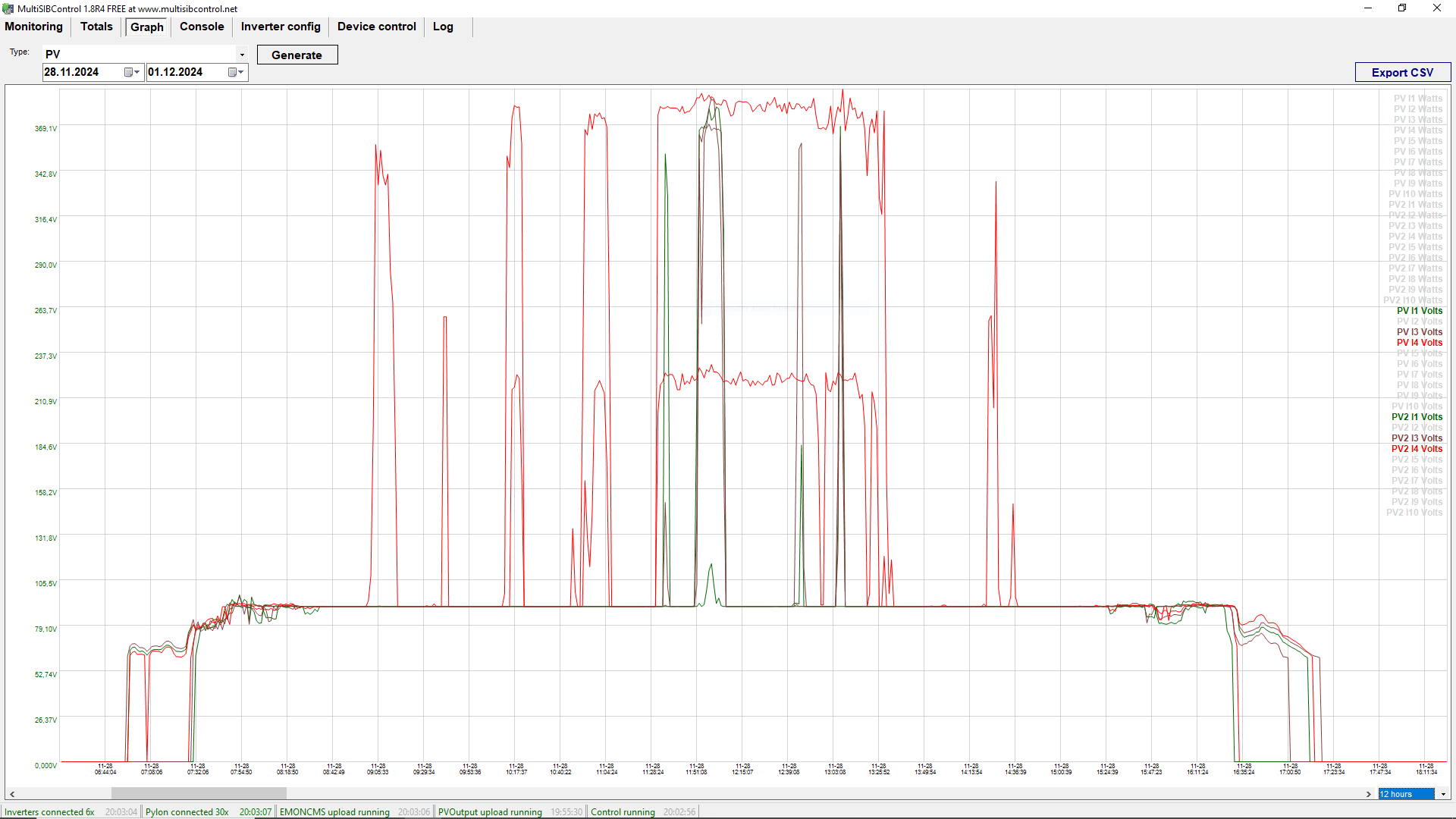
Here are my first results for firmware version V56.09 (Main) and V22.21 (Panel): a) This firmware fixes my problem that the inverters very often “forget” their parameters when restarting and then start with the default parameters (this destroyed one of my inverters in the three-phase system). b) The power management has also improved. In solar-only charging mode, no additional power from the grid is used for charging when the PV output is low. The SUB output strategy also works better now. c) Unfortunately, the PV input behaves as before. The stuck at 90V and thus a significantly lower yield has not been fixed. The PV control algorithm is also not working properly, the problem described by @Georg594 in Shadow Management still exists. A patch like Coulomb's Version 556.07 (implements a minimum MPPT voltage of 150 V) would be nice (to fix the 90V problem). If he has some time, I would like to ask him for it... When I look at my diagrams with voltage and power, I can't see any working MPPT control. The PV voltage is often far too high and power is wasted. But, the sun is now low and the PV modules are not really receiving the same amount of light.
-
Axpert Max II 10kW Panel Firmware V22.21 Remote Panel_Reflash_MCU(22.21).zip
-
Axpert Max II 10kW Main Firmware V56.09 (TMS320F2809) MAXII10K_DSP_5609.7z
-
The implementation of Georg594's Shadow Management in the firmware version dsp_556.07 (Max II 10 kW) should solve the problem. Maybe there is some time for that?
-
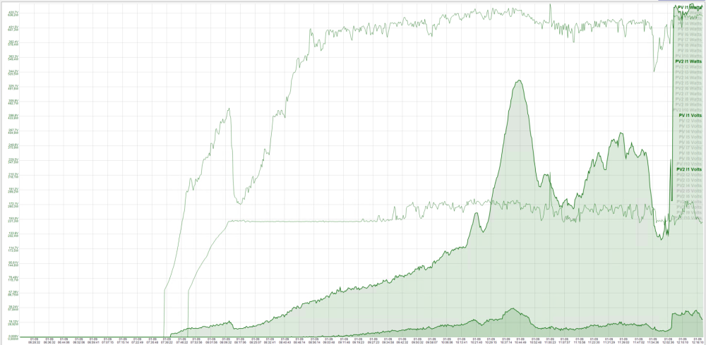
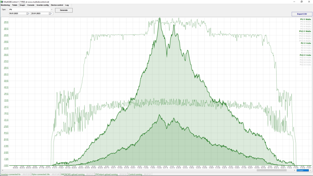
Unfortunately I was busy with other topics - sorry... I've just had a proper look at the various data for my system (all inverters are currently patched with dsp_556.07). The MPPT algorithm does not seem to work well at low currents. The voltage remains close to Vmax for a long time (Fig. 1). It does not look like the optimum operating point! I have of course looked at many older measured values (including older firmware versions) - it never looked really optimal (Fig. 2). But the problem only occurs with little sunlight (rather only indirect light). But then I just need optimum efficiency... The algorithm seems to me to be in need of improvement. Do you see a possibility for this? (Unfortunately, I was also unable to solve my problem with the “forgotten” parameters. If you make a mistake when restarting the inverter, there is a loud bang. I've already had to replace all the MOSFETs and an electrolytic capacitor in an inverter - it was a difficult job...)


-
-
The firmware works well. 👍 Unfortunately, 4 inverters displayed SINGEL after the restart as before. After setting the inverters to 3Px, all parameters were OK again (unlike before). Somehow something has changed here!? Now to the PV test (winter in north germany, no direct sun!!): (HYUNDAI SOLAR MODULE HiE-S400VG: Voc = 46.4; Vmpp = 38.6) 1. Test with 5 modules connected in series: 5 * Vmpp = 193 V a) therefore I chose the 150V version ("PV2 I1", with snow on top): looks good, no more 90V problem after sunrise. b) a further test with the 120V version showed long interventions of the algorithm with the associated fluctuations in voltage and power 2. With 10 modules in series ("PV I1", the snow on these modules had already been blown away) the voltage and output increased rapidly: no more 90V problem after sunrise. I will have a look for a few more days and then possibly update all inverters to the 200V version...
-
I went back to dsp 656.05 to generate any PV yield at all in the winter here. Just to clarify: Error 90 has not occurred (so far) and all serial numbers are and have always been ok (as I use MultiSIBControl, I can always see the numbers). The error of the "forgotten parameters" could actually have been caused by the patches. Because before our tests I had switched the system off and on many times and there was no such problem!?

-
Yes, I have seen the date. I received the firmware from my dealer (solarpower24.it) in October 2023. Ok, I wasn't very active last year (had to take care of bigger private things until now). But I kept pointing out the 90 V problem to my dealer. After I had a second serious error, I received the "new" firmware in October 2023. The error was that the inverters often (90% !) start with the default parameters after switching on (except when the battery is PYLON). This caused one inverter to break (Explosion ! and parts of the IGBTs went through the fans, a bad sound). After replacing the MOSFETS, an exploded high-voltage capacitor and an SMD resistor, the mainboard is running again. Then I pushed "a little harder" my supplier and received the "new" firmware. Unfortunately, there were no positive changes. The "forgotten" parameters are also a big problem. It took me 30 minutes to restart and re-parameterise the system. An error here will burn one or more inverters again. I would like to ask you to repeat the patch for this firmware. Is that possible? Do you have any ideas about the "forgotten" parameters? Best regards
-
-
Here is a the DSP firmware for the MAXII10k inverter: Version 56.07. Despite the information to the manufacturer, the 90V problem has not been solved! (If the voltage is clamped at 90 V and the solar field is switched off and on the voltage increases and the solar power is now 4 times higher.) "New" is that when PV power is available, the battery is also charged with some mains power (despite mode solar only): bug or feature? MAXII10K_DSP_5607.zip
-
Here is the communication protocol for the MAX series. Hope it helps. A manual you can find here: https://solarbackup.co.za/wp-content/uploads/2021/10/KODAK-Axpert-MAX-II-10K-manual-20210628-OG-10.0.pdf https://www.solarpower24.it/servizio-supporto-2-2/download-manuals-and-software-link/?lang=en Originals are here: https://voltronicpower.com/en-US/Product/PV-Inverter/Off-Grid-Inverter (I do not know anything about Growatt.) MAX Communication Protocol for HV7.2k LV5k V00 20200717.pdf
-
The firmware is now running on all inverters, it works satisfactorily with one exception: The PV array with only 4 modules only has a Vmppt min/max of 120V/170V, here the setting of the voltage naturally not pertect - the power drops. I would be pleased if a change is still possible. As already written it would make sense to do nothing below 89 volts and then only set it only to 120 V or to test the change with 10 V add - perhaps this intervention is already sufficient? It may not be enough! The power drop is not visible in the first diagram (resolution) but you can see the voltage fluctuations. In diagram B you can see it.

-
I am a little frustrated as the inverter readings used so far are not really accurate. Examples: With a PV field I always had +8 to +15 % more power than with the almost identical field, although due to some large conifers at my neighbour's I would expect slightly less yield. After switching to another inverter, the field was now mostly lower (-5 %). The PV power measurement is very inaccurate. Since I also read out the pylon readings, I see at least 500 W less charging power than the inverters report. Often the inverters show that the battery is being charged and Pylon shows discharging. There are also differences when discharging, and here too the own consumption of an estimated 150 W per inverter and the losses during charging and discharging are not displayed. E.g. after 10 days the inverters show +100 kWh (charge - discharge), but Pylontech shows only +10 kWh and SOC is almost the same after the 10 days. In battery mode, consumption from the grid is also not displayed by the inverters. I have daily losses of approx. 3.x kWh per inverter. I do not have independent measurements for an exact measurement. Actually, a measurement value recording system should be installed at all inputs (PV, grid) and at the AC output. At the moment, I can only trust the pylon readings but not the values measured by the inverter. Both measurement errors and conversion losses of up to 20% are possible. Since I have little PV power in winter and also little consumption, my total losses reach almost 50% (PV -> Bat -> AC, PV -> AC and Grid -> Bat -> AC). If I had switched off the system and thus lost the daily average of 14 kWh PV, my grid consumption would still not be higher... (But in summer I was able to supply myself, despite much higher consumption). Conclusion: I have to calculate with losses of 3.5 kWh per inverter and day. The PV measurements taken so far should be interpreted with caution, as an error of up to 20 % is possible. Self-consumption and losses cannot be seen with the measured values supplied by the inverter.
-
Yes, Georg's version is called 56.06 (based on 56.05)
-
The diode goes in the same way as the two diodes on the MPPT board in the direction of the SPS board (all cathodes to SOLAR+). Since Georg probably connected the SOLAR cables directly to the bus, my diode should have worked in the same way!? (I would have liked to minimise the 300W inherent losses of the 4 active inverters. The two inverters that are in standby mode in winter only need 10...15 W each.) _____________________________________________________________________________________________________ Your circuit is correct, by the way. PV- is connected to SOLAR- and Bus-. The two PV inputs PV1+ and PV2+ are directly connected to SOLAR+ via the two diodes.