


lcj
Members
-
Joined
-
Last visited
Everything posted by lcj
-
Got something working after hours of trying. Dyness documentation for this BMS pin out is not the same as the technical manually claims. The software I tried using before also does not work.
-
Thanks for the reply. I don't know how to share the software. Upload limit of 3MB. I have the DIP switch setting that show the different Master Sequences #1 - #6. None of the DIP switch arrangements respond, so the BMS port could also be damaged. https://dyness.com/Public/Uploads/uploadfile/files/20241023/B4850UserManualEN.pdf I'm trying to figure out why my B4850 BMS isn't responding at all on RS485 — same USB-RS485 adapter works perfectly with my Pylontech setup. I've tested multiple DIP combos (e.g., #2+#3 ON for Growatt SPF RS485 mode at 9600/115200 baud), but still no reply to any read requests. If you've got direct experience with reading registers from the B4850 via RS485 (protocol details, confirmed baud/slave ID, or a working sample frame/hex that elicits a response), any quick pointers would be appreciated — info online is very limited. Thanks! I've also not been able to find information where an inverter to BMS setup works on a standard protocol.
-
I want to read Dyness B4850 with a RS485 USB comms cable. According to Dyness manual: Pin 1 RS485-A Pin 3 RS485-B Have wiring sorted for other BMS running Pylontech, so USB to 485 working. Found Dyness software online that sends out what looks like comms to read each register in a sequence. No matter what BMS DIP settings I set, the BMS does not answer. If anyone have a working coms setup I can learn from, please contact me. The information on the net is very limited.
-
Thanks for the suggestion. I'm going to try and let the pack run down and monitor the cell voltages.
-
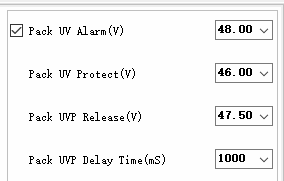
So, I was able to read out the settings I'm interested in and found it to be what I was expecting. Now it begs the question why is the BMS cutting out before reaching the UV alarm setting. From my understanding it looks as if the BMS might be reaching 0% SOC before reaching the UV setting and then switches off. I'll be monitoring it to understand the scenario under which is occurs. For now I have moved the inverter setting for back to grid up to 51V to avoid the same scenario of a BMS that has switched off. The software is available from the following website: https://shop.thesunpays.co.za/pages/technical-support . My suggestion if you are looking for the PBMSTool is to search for it and download the relevant version applicable to your Pace BMS.
-
What I have found is from Segen, where they give the spec of the battery cut off voltage of 48V? When the BMS cut out the voltage of the battery was sitting at around 48.6V, so the BMS already determined SOC was too low and switched off. I'm working on adding a monitor to the BMS to record the BMS details, I'm case this happens again. Want to ideally have my inverter talk to the BMS directly, but KODAK is not yet able to do this.
-
PACE BMS. What frustrates me is the limited documentation I can find on my battery type and BMS on the supplier website. I have no idea from the official info what the cut off voltage is. I've set my inverter to go back to grid at 51V up from 49V until I can work out what's going on. My inverter can also not interrogate the BMS for SOC, and the highest my inverter cut off can be set to is 48V. The BMS switched on again, but that was not a great experience. 5-REVOV-R9_220Ah_SpecV3.pdf
-
Hi, How do I start the BMS up again after it has reached the 48V low voltage cutoff? The inverter cut off was set too low, and the BMS switched of at 48V. Now, when I turn the BMS off, and back on, the start up sequence occurs, and then ALARM LED comes on to show the low voltage condition, but the BMS does not switch on to allow the inverter to charge it again. Should I just use the receded RESET pin on the front panel of the BMS to reset the unit? https://revov.co.za/2ndlife/revov-2nd-life-r9-lithium-iron-battery/
-
I want to know if someone has been able to read values from IG3N batteries?
-
@tertiuscpt, happy to report that I got it working by getting the right RJ12 connector for the RS232 port.
-
I'm thinking it is either a PACE BMS or CAN BMS. Revov's earlier model the R100 looks very very similar. The biggest difference is the BMS is built into the battery on the R100. @tertiuscpt, I want to confirm, the BAUD is 9600 by default on bmspace software? How would I set the BAUD to say 2400 @reapster mentioned earlier in this thread the RJ11 jack of the R100 pinout, so I'm hopfull the R9 with its 6S6C type, would most propably have the middle two conductors be TXD, and RXD. Will be finding a RJ11 with 6 conductors and experimenting with it. Attached a picture of the front of a R100.

-
I have a Revov R9 with what looks like a PACE BMS and tried to use the pacebms code but RS232 and RS485 is not responding when sending out serial commans. I'm not sure which port to use for USB to RS485.

-
@PearlJam, It would be nice if we can have that confirmed by the supplier in some way. The warranty wording on my batteries does not read like this. Thinking about the way other BMSs are also counting it twice, makes me wonder why the one battery then counts only 1cycle and the second battery 2cycles. If it should count 2 in practise, then it should be consistent on both.
-
Hi @tertiuscpt, I agree with you the way the cycles are counted is not accurate, and the only thing they will do when you have a warranty claim, is say "Sir you reached you 3000 cycle". I want to connect to R9 2nd Life Revov batteries via the R9 C8 Pace BMS to monitor it. Will send you a private message on how to get it working. I think it is important that you gather more evidence and maybe let the battery run to complete DOD a few cycles while monitoring the count. Then do a few 50% discharge cycles like you did and send through your results. This is more than enough evidence to start an investigation. I can even have people in my area I know contribute and I have them monitor the same on the batteries they have. If this is a the norm rather than the exception, we have to speak up as it is a large investment.
-
Installed new inverter and left all factory settings in place except: 1. Output Source Priority to: SBU (Programming Option 01) 2. Utiliy Charge Maximim Current: 10A When AC Input Source for Utility switches ON or OFF, and it causes the inverter to change from Battery to Utility or vice versa during load shedding that initialises or manually switching it on and off on AC Input, the AC Output switches off temporarily. I don't notice any fault conditions on the screen. Is there a way to know if the inverter is in fact faulty and need to be returned?
-
That's perfect and it makes sense to me now what's going on internally.
-
This is from the manual from KODAK:
-
Ok, so what would you suggest I do. I have gone through the latest manual provided by KODAK. I'm looking for the Axpert manual now to see if it mentions anything more specific. For me the question is not software related, but hardware related in how the wiring can be done on the two available AC outputs. My electrician does not have sufficient knowledge of the dual output inverter type I have and from referencing the manual to know what is a known good configuration. What does the internals usually look like. I've glanced over the following post that show the input / DC Bus / Output schematic. I wonder if the total output power of 6.2KW is rated over the DC Bus, and each AC Output can provide 6.2KW by itself if the other is not used, or if both are in use, the two outputs together cannot exceed the 6.2KW? Referring to this post: Axpert Schematic diagram
-
Hi, I'm finding very little information on the inverter with dual AC ouput. The marketting material mention essential and non-essential output arrangement. Configuration 1 - Drive Essential & Non-Essential load via output 1 & 2 respectively on two seperate output circuits. Configuration 2 - Drive Essential & Non-Essential load via output 1 & 2 together, basically combining the output power over two outputs and driving one circuit with both essential and non-essential tied together. Configuration 3 - Drive Essential & Non-Essential load via output 1 ONLY. Does this limit the output power over the output 1 by not using output 2?


