


CptH4ppy
Members
-
Joined
-
Last visited
Everything posted by CptH4ppy
-
If battery power is availible the inverter will pull up to its max capacity from the battery. (So 5kw for a 5kw inverter). If you go over that limit and grid is availible the difference will come from thw grid which you will be paying for. All the power will be going to the load.
-
Has anyone else noticed that firmware on their inverters are being updated without an update being requested? It's happened to me 3 times in the last 2 weeks. The only reason I know is because I have a parallel system. 2 x 5KW units. When one of the units restart the other one freaks out because of the missing comms connection and then it cuts the power. This was pretty hard to figure out because the only error I see is "F29 parallel comms failure". Only on the inverter that restarted first. And it only happens a few minutes after the grid returns after loadshedding. I had a feeling it might be firmware related so when it happened today I snapped a photo of the firmware version to compare when it happens again. When I checked a few minutes later the firmware version had changed. On the primary from 3384-07C4 to 3384-081B and on the secondary from 3384-0782 to 3384-080A. Not to mention the issue with them having different numbers. They use to be the same. I might be wrong and the last 4 digits mean something else. I'm thinking of plugging out the WIFI dongles to see what happens so nothing can be pushed to the units. Anyone experience anything similar?
-
Not sure about the 12KW. But I have 2 x 5KW units and for me it's separate. If the charger is set to 100A and there is a 5KW load in the house the inverter will pull 10KW from the grid side (5KW for the charger and 5KW for the load). You can limit this by setting up grid peak shaving on the inverter. This will limit the total power taken from the grid at any point. So if I were to set it to 6KW for example and there is a 5KW load, the battery will only charge with 1KW. edit: Just to add. If you were to set it to 6KW in the example and you pull 8KW on the load side, the inverter will draw 6KW from the grid and the other 2KW will come from the batteries. And this will only happen when the SOC is lower than the SOC in the System Mode screen. But all of this is just from what I have noticed on my setup.
-
(Part 2) The Application Manual of 48V series Lithium iron phosphate battery modu....pdf
-
@Tech_in_the_Dark Here you go. (Par1) Schematic diagram of dial switch for CAN Comm Type (host address_1).pdf
-
@Tech_in_the_Dark Just some quick feedback. First National Battery don't import that battery anymore. Apparently it was one of the first rack mount units they brought in. I have the manual for the one they currently sell but it looks very different. I'll add it anyway if someone needs it. There is a guy at First National Battery that has the right details for the battery you have. I'm just waiting for him to give me a call then I will post the details. User Manual 5100.pdf
-
I agree. Also have a newer battery with 6. Go with 1 0 0 0 0 0 if you only have one battery.
-
Looks like the same BMS as all the other batteries out there... Maybe try the following: Dip switches: 1 0 0 0 Select Lithium from the battery tab in inverter settings Select protocol 0 I cant see the whole battery in your picture but I'm pretty sure it has a CAN port. So select CAN in settings and connect a standard network cable to invert CAN. Go back and select Li-BMS from settings and see if you see a charge and discharge value. If that doesn't work, I have some friends at First National Battery. I can get you the details on Monday.
-
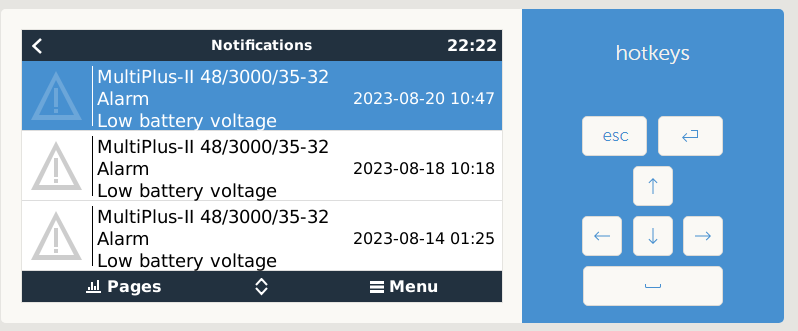
Just wanted to know if this is normal? Or if I should be worried. I have a multiplus 2 installed with a 5.12kwh BSLbatt battery in a ups setup. Everything seems to work fine but every few days the I get a low battery warning from the multiplus. No errors from the battery though. The installer says it is a firmware issue and that we shouldn't worry about it. Can it be something else? Has anyone else seen this? Thanks in advance.
-
I think you might be right. I am considering just ripping out the solar collectors and using the heat pumps on their own. The setup is a lot simpler and I have a large PV setup so running them isn't a problem. The other idea I have is to leave the existing setup intact and add an additional geyser is series for the heat pump. So the solar one will feed the heat pump one with preheated water. But there might be some space issues with this and it's more expensive.
-
I need a better understanding of how this would work together. I'm sure someone on this forum has a similar setup to what I would like to do. I have 2 geysers. 1 x 150L and 1 x 200L. Both have geyserwise units with a flat plate connector. This has been working fine for 5+ years without much maintenance. But I still use the elements in the early mornings and sometimes in the afternoon if we didn't have enough sunlight that day. I would like to add 2 x 4.5KW ITS Solar heat pumps to this setup but still keep the original geyserwise units intact. So when the sun shines the geyserwise will circulate the water through the solar PV and when needed the water can be circulated through the heat pump. I'm just not sure how all of this would need to be piped together. Any help would be much appreciated.
-
After another look it looks like the contactor is fine. I'm guessing the reading is just weird because one inverter is grounded and the other not. I will ground the inverter and test again.
-
Ok. Hold on to your hats because this is getting interesting. I opened the front panel of the inverter to check if the earth is attached. There were 2 wires connected for earth. One for input and one for output. I tested for a voltage difference between the earth terminal and the earth bar inside the DB and there was 110vac. I opened up some of the conduit to traced the wires and found out that they are not connected to anything. The wires just stop in the middle of the conduit. The main inverter does not have an earth at all. I'm guessing this was an oversight as the second inverter has it's earth wires connected to the earth bar in the DB. Secondly I think the E-N bond is the wrong way round. i.e. it bonds earth to neutral when Eskom is on and disconnects it when Eskom is off. If I measure for voltage difference between the E and N wires that are connected to the contactor I get basically 0 when Eskom is on and 110v when Eskom is off. But this is something I am not sure about so please help me here. Thanks for all the help so far.
-
I will open the unit when I get home this afternoon and check the earth connection. As far as I remember there are 6 wires connected. LNE on input and output. I might need to trace that earth wire to see where it goes. Maybe it is disconnected somewhere else. As far as the E-N bond is concerned. The setup definitely has one.
-
I think this is probably it. There is no ground wire connected under the chassis like the one in your picture. Thanks for the help.
-
A little more feedback. There are 4 seperate breakers at the inverters. 2 for input and 2 for output. Even with them all down so there is no power in and no power out to both inverters I still measure the voltage on the primary inverter chassis. There is a 2 pole contactor in place that Im guesing is for the E N bond. I can hear it disconnect after turning eskom back on after about 30 seconds.
-
Just to be clear. This happens when Eskom is on or off. And I am measuring from one of the screw holes on the front of the inverter.
-
I just have a quick question that I'm would like to ask here before asking my installer. Just so I have a better idea about what is going on. I fear they might make it out to be nothing. I've had my parallel 5.5kw Sunsynk setup for about a year now without any problems really. It is your standard grid tied setup with panels and batteries. Today I was changing a light fixture with all the lights breakers turned off and get a shock from the neutral wire. I measured it and there was about 110v between E and N. In hindsight I should have just completely disconnected the power but the wife unit would not approve the request. Anyway, after a few more tests it seems to me the problem is coming from one of my inverters. When I measure from the chassis of my master inverter to ground I get the same 110v. That's with Eskom switched completely off. There is no voltage on the slave inverter chassis. Any idea what it might be?