


AndrewF
Members
-
Joined
-
Last visited
Everything posted by AndrewF
-
The IGBT referrences QB QA QD QC

-
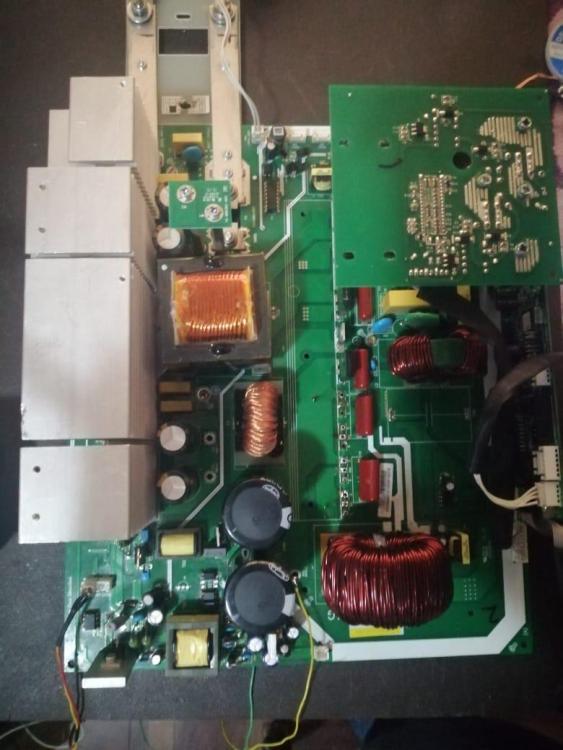
Please confirm if i am correct that IGBTs QB + QA are switching sinewave and IGBTs QD + QC are switching square wave pulses in the inverter shown..
-
A question , could a circuit using a SG3525 PWM driver be used in this test idea using the PI circuit you created or does the PI perform other functions apart from supplying switching pulses..
-
Hi I read through your explanation again and seems I might have misunderstood your message, apologies if this is the case.... did you create a makeshift DSP controller, ?? that switches high and low IGBTs in a test simulation...and monitors I would need to find and remove the high speed bridge diodes between DC to DC converter transformer and BUS side ..as well.. A the FETS are still in place and DC to DC converter,,
-
Hi i found this at Mantech https://www.mantech.co.za/ProductInfo.aspx?Item=15M9393 EGS002 EG8010 a sine wave module , there's an application note as well, https://www.mantech.co.za/datasheets/products/EGS002_IR2110S.pdf this might be a better option to Raspberry Pi ?? , this is what I want to try personally, if DSP is damaged, but I have the controller(controller worked on another machine) and want to trace the sine signal from source, mentioned an open collector connection to main board but didn't mention pin no or location on connection plugs(where DSP plugs into main board), it would be great to know where to start tracing , possibly the DSP did get damaged....
-
Hi this screenshot is part of sharing post on starting up PWM ic without battery side FETS present, can the same be done for the tracing/testing of sine wave pulses for IGBTs on the bus voltage(450v) . The IGBTs are removed But the battery side FETs are present. the battery side pulses are fine BTW.. https://forums.aeva.asn.au/viewtopic.php?p=65282#p65282

-
I am hoping someone can put light on where the sine wave generation takes place, I would like to trace from sine wave creation circuit to opto isolators..
-
On this 3Kw Inverter I'm now busy with Dc to DC SMPS, In the service manual 3.1.3 Divers there's a photo showing trannies and a 8pin chip right in the middle of the heatsinks.. , between UC2 & UC4 driver transistors for fets, there's a 8pin SMD chip which connects SG3525 PWM chip to the fet driver transistors. Any ideas what this 8 pin smd chips purpose is ..........
-
I'm looking for waveform screenshots on input pins on all optos driving the Inverter IGBTs if anyone has captured them for reference.. some of the waveforms on this board seem unhealthy/not good.. Many thanks to Coulomb and BritishRacingGreen for your valuable input shared above ..... this Will No Doubt help many members going forward with this valuable topic....
-
BTW i removed all the op amps and most of the chips checking voltage each time...
-
I'm looking for waveform screenshots on input pins on all optos driving the Inverter IGBTs if anyone has captured them for reference.. some of the waveforms on this board seem unhealthy/not good.. Many thanks to Coulomb and BritishRacingGreen for your valuable input shared above ..... this Will No Doubt help many members going forward with this valuable topic.... so somehow i selected the incorrect reply box , LOL , anyway . the last issue was -12V pulled down by......, i found a damaged TL074 as well as 16V Zener short circuited(removed both), for IGBT gate driver, and -12V is back(whew, relief.....) not sure which one caused it . I forgot to check -12V before and after these 2 discoveries .. but getting there it seems, will get replacements and start looking(scoping) for sine wave and switching waves respectfully..
-
I replaced both caps and short still present.....pulling -12v down to -1.5V
-
Does anyone know what the -12v supply is used for ......I need to isolate this area to find shorting problems...
-
Ok so there no 100uf caps around the 79L12 only a 47uf , so will try that one
-
Thanks will replace C116 and hopefully solve the problem......
-
Hi im checking waveforms without IGBTs present(don't want to blow new parts....), but thanks for the interesting point.......Nice to know... i was going to create a photo montage of the board with waveforms while running/switched on generating 230V AC for future reference.
-
Hi all , next to the display cable connector there's a 79L12 neg regulator, the output of regulator goes short circuit at power on but no short while no power ....does this power what i wonder.... , whats shorting this neg rail ....need to trace the reason for -12V,
-
I'm looking for waveform screenshots on input pins on all optos driving the Inverter IGBTs if anyone has captured them for reference.. some of the waveforms on this board seem unhealthy/not good.. Many thanks to Coulomb and BritishRacingGreen for your valuable input shared above ..... this Will No Doubt help many members going forward with this valuable topic....
-
I'm looking for waveform screenshots on input pins on all optos driving the Inverter IGBTs if anyone has captured them for reference.. some of the waveforms on this board seem unhealthy/not good..
-
Hi Is smd code E43G same as TL431 , have found cracked casing E43GIs smd code E43G same as TL431Need diagram for this (it looks like a Voltronic Axpert). Inverter IGBT ipto voltages -5v & +15v....Nedd
 Hi im hoping to find a circuit diagram or manual showing the origin of -5V and +15V supplies for the opto's switching IGBTs in the AC conversion circuit...


