AndrewF
Members
-
Joined
-
Last visited
Everything posted by AndrewF
-
I'm using norsk cable between enclosures
-
If I mount a weatherproof enclosure vertically with a seal on the lid and fit waterproof glands on the left and right sides of enclosure to connect between lights is this legal Thanks for any advice
-
Which brands do this form of bucking the solar input voltage to acceptable bus voltage for 400V versions and buck solar input voltage to battery input voltage for the 145v versions..
-
Based on this explanation will a 145v max model voltronic buck say 40-45v up to 49v for battery input it there is enough current supplied by panels(direct sun exposure)
-
Do all high PV Input (500V) Hybrid Inverters follow this block diagram where PV input is connected to the HV bus..
-
are there losses converting 400v to 48-50v battery levels input of inverter, if so what is the loss % down converting 400v PV input to battery levels
-
As I understand it the 400v PV input is converted to battery input levels by the MPPT, please correct me if I'm wrong. Apparently 400v PV input models do not send the 400v to the bus side after the DC to DC circuit,
-
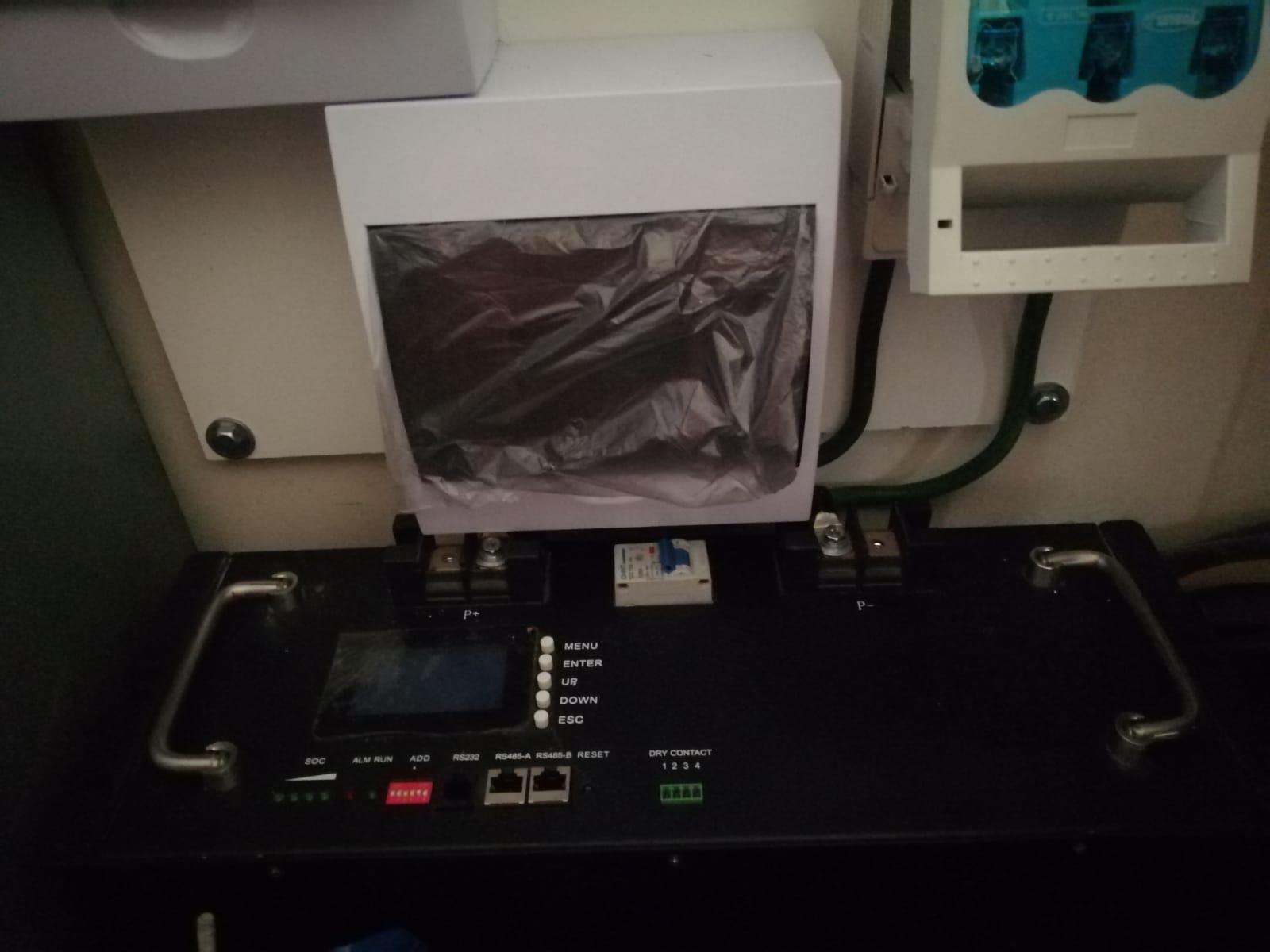
I was explaining which battery I needed info on how to shut down BMS and so shut battery standby power off.
-
Apologies for the Leoch battery discussed here
-
Hi @Scorp007 or anyone else.. do you know how to switch off battery BMS off to switch battery off completely.
-
Thank you @Scorp007 you had the answer I needed.
-
There are no solar panels connected to this setup ATM.
-
Hi I'm posting photos of specs of Inverter as well as battery, there is no name on the battery ! , I'm hoping someone will recognize the make .
.thumb.jpeg.e4066319e7145f8a216526e13ffa0ad1.jpeg)

-
Hi Coulomb, I've been wondering lately if its possible to set a 5 Kv Axpert to AC charge but not activate inverter mode at power fail if house is unoccupied and no one using power in the day. IOW the house owner would have to activate the inverter if the power was out once arriving home, Its pointless for inverter to run if no one is home and needing power.. My fridge manages to keep cold fine during load shedding..
-
There is no solar charger connected during these tests, the fact that the soft start is reaching 600v with no other input voltage other battery is very concerning, Ive already blown IGBTs as a result... Is there any mod available for the FB of the PWM IC to limit/regulate the soft start voltage..
-
According to the soft start circuit should get to 315v, unless I totally misunderstand the context of this post,. my soft start has already blown blown IGBTs , The voltage is exceeding 600V, is there any modification that been done to the FB to regulate this voltage ...
-
Hi Coulomb, so I got the soft start circuit running, but because I have no AC converter IGBTs present the circuit goes into "error 53".. and the soft start circuit resumes again driving the bus caps up to 600V odd. ...that got me really worried... Is this normal for the soft start resuming after an "error 53" on the DSP..
-
Ok yes things Are going somewhere....where would I find the 3.3v power supply..
-
you seem to have answered this Q already....
-
So I removed the ULN2003A and measure pin 3 pad at 1.1V positive relative to CN10-8 for about 1 second then pad 3 voltage is off, as far as I understand ULN2003A only outputs a signal while there's an input... Could there be a menu setting that can affect the DSP not sending a positive signal to the ULN for soft start power supply
-
Hi Coulomb you mentioned on another thread that if 2 inverters were previously set up in parallel that the soft start circuit in the inverters is disabled. Is there a setting to confirm this on the menu. I previously had to set one inverter from "Slave" to "Master" if I remember correctly because it showed an error stating that it was set as a Slave or parallel unit .
-
Hi Coulomb, After thorough double checking , connecting CN11 pin 14 to positive multimeter lead and ULN2003A pin3 to negative MM lead on power up I get 11.38v reading, ULN not switching(closing circuit to U17) because a low is on ULN2003A pin 3 not a high, should I configure a PNP to switch around +3v to ULN2003A pin3
-
on the schematic I have there is no trace between CN11-16 and U13...Ok the schematic is incomplete, there is a trace that stops at R261 and simply marked to CN11-16
-
I measured the processor signal at ULN2003A input pin 3 (which feeds output pin 14 which connects to CN11-14) , with reference to CN10 - 6 which is GND and CN10 - 9 which is +12V, And discovered that input at pin 3 and CN10 - 9 gives a multimeter reading of +12V at initialisation/power on.. I am trying to figure out how this low/GND gets the ULN20033A to send a low , it just doesn't make sense... Your top statement makes sense But there's a low signal going to pin 3 for around 10-15 seconds then it turns off...Turning off the soft start power..
-
It appears that ULN2003A is meant to switch high or positive signals/voltages, not lows or GND signals, that's what I understand from you tube descriptions and application circuits... Unless ULN2003A is used differently in this application by Voltronics

.jpeg.ce52f833d2d86800d0f5f070409141fa.jpeg)