


AndrewF
Members
-
Joined
-
Last visited
Everything posted by AndrewF
-
From pin 3 to pin 8 on ULN I'm getting around 6 k . The DSP sends a low signal for around 10 seconds at power on then the low signal resets which corresponds to the idea that the soft start circuit switching off before the DC -DC circuit generates the BUS voltage , and the BUS caps would be charged up already, and the DSP "thinks, All Ok" as the pre charge of caps took place,. The DSP does not seem to send a high based on your notes but a low which based on my circuit makes sense as there is a +12v already at the opto and the low from the DSP will activate the Opto , But the ULN2003A sending a powerful low isn't making sense....

-
According to the circuit I have the DSP CN-14 is switching low to U17 pin 2 and pin 1 on U17 has permanent +12v from sps , the low input from DSP would activate the soft bus power supply..soft bus power does work, already tested shorting the opto U17 output.
-
According to data the ULN2003 on the DSP board only switches high signals where as a low signal is sent to the chip from the processor...
-
ON the DSP board I traced CN11-14 to the ULN2003 chip output then to its corresponding input, and soldered a test wire at the ULN input so that I could measure a low or GND on power up once DSP plugged into main board .... On power up I get immediate GND connection on the test wire on DSP relative to U17 pin 1 measuring expected 12 V. I then check CN11-14 again , power down , power up then GND works fine at CN11-14, then I get ready to test Soft Start BUS circuit and.... once again no GND on CN11-14 at power up... did some research, but all explanations on ULN2003 show +ve input switching on ULN not GND input switching, with 5V + at pin 9 and GND at pin 8, I cant trace any connection at pin 9(measuring power on pin 9 with board plugged in is impossible IMO) .. Any thoughts...
-
1. Hi Coulomb , how do I hold the processor in reset state ... ? 2. Are there any conditions on the main board that can stop soft start circuit from testing for shorts by pre charging BUS caps ?
-
-
Is there a schematic of the DSP Module board for these Axpert 5Kw inverters, I need to find why there's no low signal via CN11-3 to switch U17 on via pin2 to pull U16 pin 2 ( FB )low to enable the BUS soft start SPS to operate and pre charge the BUS caps.... U17 has 12 V on pin 1...And the BUS soft start SPS has about 13.5V on U16 pin 7. Any thoughts why the DSP module not switching a low via CN11-3 to U17 pin 2.. ? Not sure if other inputs are required on the DSP board to allow the low signal from CN11-3 to activate Opto U17
-
So on my own journey with the Axpert 5kw , I have discovered that this reference voltage that has mentioned here does not get pulled low by the DSP, is there another process that causes the DSP to pull pin 2 low on U17 thereby pulling FB pin 2 low on U16 . There is 12V present on pin 1 of U17 BTW, so pulling pin 2 low on U17 will do the trick...When the unit is witched on after some time the DC to DC converter does work generating 425V , but the soft start does not precharge the BUS caps......The unit switches off after about 2 seconds when the 425V is generated on the BUS....I have removed the BUS caps for this part of the repair... Any thoughts please.....
-
I also removed TX7 to check it...using a desoldering technique shown on You Tube where a thick 2.5mm dia piece of solid core copper wire is wrapped around All the pins in a row then with powerful Iron and added solder, the whole area is heated up to release the soldering of one side of the transformer, the transformer is then simply pulled loose carefully and same procedure is repeated on opposite side still soldered to board....the result was a perfect unsoldering of TX7...The last time I tried similar thing I destroyed tracks and pads so went looking for ideas...
-
On the schematic for AC conversion U3 & U1 T350 IGBT driver opto's have 820nf ceramic caps across pins 5 & 8 , I damaged /lost these caps when replacing opto's , If I use 1mfd ceramic caps replacement would it be ok ?? I can't source 820nf...
-
The whole inverter shuts down with alarm as the AC voltage reaches between 150v - 200v AC , but no error codes shown... , I'm busy reading through "A journey Started" hoping to see if he experienced a similar problem.. I removed the BUS caps measured them and they fine.. There might be a feedback voltage issue where the processor can't monitor output levels although the display shows the output voltage. I tested the few series resistors that appear to be a feedback system but need to study the schematic to confirm this, I was just hoping that the problem was common and fairly "easy fix"
-
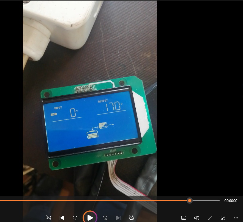
The inverter started up normally then at around 200V output switches off ..
-
Hi so I have managed to get the AC circuit to start up, though when it reaches around 200V AC the DSP board shuts it off again.... I wonder what that could be...I remember at one stage the BUS voltage went to around 399V DC now it seems to go up to 425V DC , is there possibly protection circuit kicking in... Any ideas please... BTW this model is 145 max solar input...5KV .....48V
-
Hi I am now working on the other 5kw board that seems to have correct waveforms on IGBT gates, but I'm very keen to try your method as it will limit damage to IGBTs....with bus voltage starting at 25vDC up to 120vDC using an external PSU to check if IGBTs are indeed switching properly . Would disconnecting DC to DC mosfets gates from the driver pulses circuit which drive the DC to DC mosfets ,No pulses no DC to DC conversion on battery side..
-
Hi , firstly thanks so much for your early post of this block diagram, 2ndly apologies for forgetting to thank you earlier for the post...(honestly totally forgot, too much on my mind...) This block has been a huge benefit for my tracing of the sine and square wave sources...the signals are all at the inputs of the opto's . U1 and U3 are working perfectly sending perfect waves to respective the IGBT gates. U2 and U4 have high voltages in place of the 15v(pin 8 ) and -5v(pin 5 ) supplied by the three power supplies around TX7 , I'm assuming faulty caps or diodes are linking these rails to the BUS side, unless I'm misunderstanding something.... haven't had a chance to trace that yet.. getting home too late..
-
According to Maxos schematic... Opto's U2, U4, U12, are getting 15V and -5V from TX7 and ZD3 and ZD4 respectively. I'm not getting correct voltages here. At switch on voltage on ZD4 5.6v is -2.5V and once DSP board activates sine wave this voltage increases to -170V, these voltages should be at -5v on ZD4 and 15V on ZD3... its strange that it increases to -170 only when sine wave signal activated by controller board. mentions in one of his submissions that he rewound TX7 , I don't remember the reason for the TX7 rewinding .....was it to solve a similar problem ???
-
Hi on the AC conversion circuit all the IGBT are measuring the required -5V at their gates on startup except for QA1 which has no voltage on the gate, any ideas what normally causes this problem ?
-
Hi can the AT350V opto be replaced with TLP350 , its all I can find ATM.. And for D8, D7, D48, D4 on AC converter IGBT driver opto output , I used a SMD value decoder on Google and not sure if I have correct diodes in place at output of opto's, no output on gates , possibly incorrect part versions/No's ?? Waveforms are present at input circuit of opto's driving IGBPT's on AC conversion circuit (many thanks to for the schematics), I'm working on this unit as I find time.....haven't worked on it for a while....It's more of a challenge for me at this stage. But will be great to figure it all out..
-
Where do i find Maxo's 10g schematic please
-
Hi is CN11-1 the connector that connects/plugs the DSP board into the main board... I need to confirm where the signals come from to pulse the LED on U1 as on my board only QB has sine wave pulses
-
Hi would it be possible to isolate the DC to DC SMPS converter mosfet gate pulses so that there's no switching on DC to DC converter and therefore no BUS voltage and then do test method injecting RasbPI signals into IGBT inverter circuit. So use the inverters SMPS to power all circuits instead of using external power supply to power up as described in journey of repairs....., the only external power supply would be the 25v - 150v DC injected into the BUS to confirm that IGBTs are working OK.. Just a thought.....
-
I use Stainless Steel(solder can't/won't tin SSteel) Electric fence wire holding solder iron on opposite side of pad to to heat up solder then push through towards the solder iron. Works very well, after struggling as much with "solder balls" jammed inside pads/vias....
-
Which GND should/must be used on the scope probe to measure signal input on the opto isolators driving the inverter IGBTs...
-
Thanks that makes total logical sense now, As QB has sine wave But QA doesn't have , need to trace where that opposite cycle wave has gone missing !!
-
P.S. I removed the large black cap in the manual photo in the top photo of unit I'm busy with..

