Enrico Zanolin
Members
-
Joined
-
Last visited
Everything posted by Enrico Zanolin
-
That's a great suggestion. I had toyed with that idea but stupidly worried about "what if you are sending a low bit, then the transceiver is not active" but upon reflection now, deactivating the transceiver would be equivalent to sending a low bit. Thank you.
-
Just a random though, I had issues with asserting the read write pins on the 485 transciever. I would set it high to write my data then set it low after the serial.write. Problem is that serial.write is non blocking and buffered so I was asserting the read write pin before all the data got out. one easy thing to do was a stream.flush() or Serial.flush() just to test. This is a blocking call and only returns once all the data is gone. I don't like blocking code so after that I implemented a buffer check to see if the buffer is empty before switching the transciever back to read mode. Even then it seems bits were still in flight so I still issue a flush but at least this way it keeps the blocking time to a minimum.
-
Just my 2 cents on what you are seeing. These seem to be requests from the Modbus master to the device with address 1 asking for data 01:03:00:01:00:02:95:CB 01:03:00:33:00:01:74:05 01:03:00:34:00:02:85:C5 01:03:00:70:00:01:85:D1 01:03:00:71:00:01:D4:11 01:03:00:72:00:01:24:11 01:03:00:73:00:01:75:D1 01:03:00:74:00:01:C4:10 01:03:00:01:00:02:95:CB 01: Device address 01 03: Read multiple Holding Registers (this is a ModBus Defined Function). 00:01 Register address 1 (the "variable" that we are after). 00:02 Number of registers (this would get 2 16 bit registers and would result in a 4 byte response). So actually you would be getting register 1 and 2 95:CB CRC Checksum of whole message. Given their structure these ones look like they could be responses from the Device on address 1 01:03:02:00:32:39:91 01:03:02:00:C0:B8:14 01:03:02:01:E0:B8:5C 01:03:02:01:F4:B8:53 01:03:02:02:44:B9:17 01:03:02:03:E8:B8:FA 01:03:04:00:04:45:C0:89:32 01:03:02:00:32:39:91 01: Device Address 01 03: Response to "Read multiple Holding Registers" 02: Length. (qty of bytes to follow) 00:32: first value of 50 39:91: CRC checksum 01:03:04:00:04:45:C0:89:32 01: Device Address 01 03: Response to "Read multiple Holding Registers" 04: Length. (qty of bytes to follow) 00:04: first value of 4 45:C0: second value of 17856 89:32: CRC checksum I have just completed building a rudimentary Modbus class and RS485 sniffer for ESP32 on Arduino for my own nefarious purposes. I would be more than happy to share it if you want to go that route (you will need an ESP32 and a RS485 transceiver). In practice I have noticed that the length stipulated in frame responses is for X octets not X words so if the length is 8 its 8 bytes or 4 int16's whereas in the request you ask for X registers which will return X 16 bit words or X*2 bytes. I find the documentation around this to be unclear so I am leaning on what I see on the bus for the meantime.
-
From what I have been reading there seems to be a requirement to bond inverter neutral to earth but only while the inverter is islanded. This can usually be performed by the inverter internally or via a dry contact signal from the inverter to an external contactor. I have many observations and questions. This would seem to solve the following... Earth leakage detection breakers on the inverter output with a functional earth(FE) will no longer immediately trip. An ELCB socket tester will no longer show a disconnected earth while islanded which raises alarms with people who issue CoC. An ELCB socket tester will be able to leak current to earth(when you turn the little knob) and cause a trip as expected (also and issue with CoC). *Note All tests pass fine while the inverter is passing through grid power. However, some inverters do not have an internal neutral/earth bonding relay or a dry contact that indicates inverter operation, some have a dry contact terminal that is only for generator signaling based on battery state. Observations... A shock hazard exists between a live terminal through a human to ground because the ground is a return to source path which is created by the existing neutral/earth bond that is normally made by the utility. If inverter outputs are floating (not connected to earth) there is no return to source path via the earth. Even so, the installation of a RCD on the inverter output would ensure tripping of the source current should there be sufficient leakage out of the system to be harmful. If the RCD does not operate it means that there is no danger for it to mitigate. I question the practicality of the neutral/earth bond on an isolated system and even though I think it best to install a RCD device on the inverter output, to some extent I also question that too (assuming the inverter input passes through an RCD device). Is a Neutral/Earth bond required for generators as well? What about stand alone wheel around generators? Why is this bonding necessary? It seems we are just re-introducing a shock hazard for the sake of simplicity of testing. One option would be to use a normally closed contactor that is kept open by the utility power and then drops closed when the utility power goes away, this however runs the danger of creating a permanent secondary Neutral/Earth bond should the contactor coil fail(which will happen at some point) and from what I can tell this is not allowed. If it were then one could just go straight to that setup with no contactors/relays(as some do) and be done with it. If the answer is that the missing earth bond feature on an inverter makes it illegal to operate then that raises the question of how can reputable established mainstream South African suppliers be allowed to sell such a thing. Side note, who the heck invented Samite/Mini Rail. I see that some are sold into the Australian market but nowhere else that I can see, and I cant find any documentation or specs on the standard. The only thing I can tell so far is that it seems to very much be a CBI thing and that other vendors also make Samite as an alternative to CBI (addressing a captured market). Where does the name even come from. I welcome your corrections of my ignorance
-
ESP32 Stuff thats done Multicast DNS for local access Enter setup/update mode when there are no settings (new device) or by long pressing button on power up. Settings saved to EEPROM and some versioning stuff Automatic captive portal redirect Firmware update via web interface SSID scan and touch selection CAN debug mode makes all CAN messages available in browser console. Async web server used for setup and operational mode Async library used for websocket server Canbus hardware and software can read data and report inactivity. Websocket client implementation for cloud streaming Message validation to prevent malicious users from pushing bad data into the cloud. Stuff to do Collect and bin realtime data into aggregated, min and max values and send every minute over websocket connection. Cache X messages locally if server unavailable and send when it is. Locally maintained totals of energy in and energy out for the last X cycles for non-cloud display. Currently using external i2c CAN controller, ESP32 has a built in one and we should try get that one working. Add RS485 hardware and all the code to run that. Add settings panel, right now the canbus runs at 500K and there are no can-id collisions of the same ID meaning different things, but this wont last. Need to at the very least be able to set data rate and possibly choose a CAN profile. Developing RS485 and talking to inverters will definitely require profile options. Ability to associate a device with a cloud account from the device local interface (this is currently a static mapping) Consider a physical display for the unit itself, needs to be cheap and not rubbish. Server Side Stuff that's done Login page (yay). Realtime terminal UI control. Node.js server for device connections and user interface interaction. Stuff to do Tidy up the site layout, this was just a 1 night slap together Allow signups and validate users. Password reset stuff. Allow naming/editing of associated units (hex numbers are only fun for some of us) Collect and log 1 minute data to RRD graphs Display/Navigate RRD graphs Only allow authorised users to view their device streams (framework is there to ensure this, just need to implement) Potentially allow remote firmware upgrades, should be possible inside the existing framework. I'm sure there's a ton more, that's just what's on my current horizon.
-
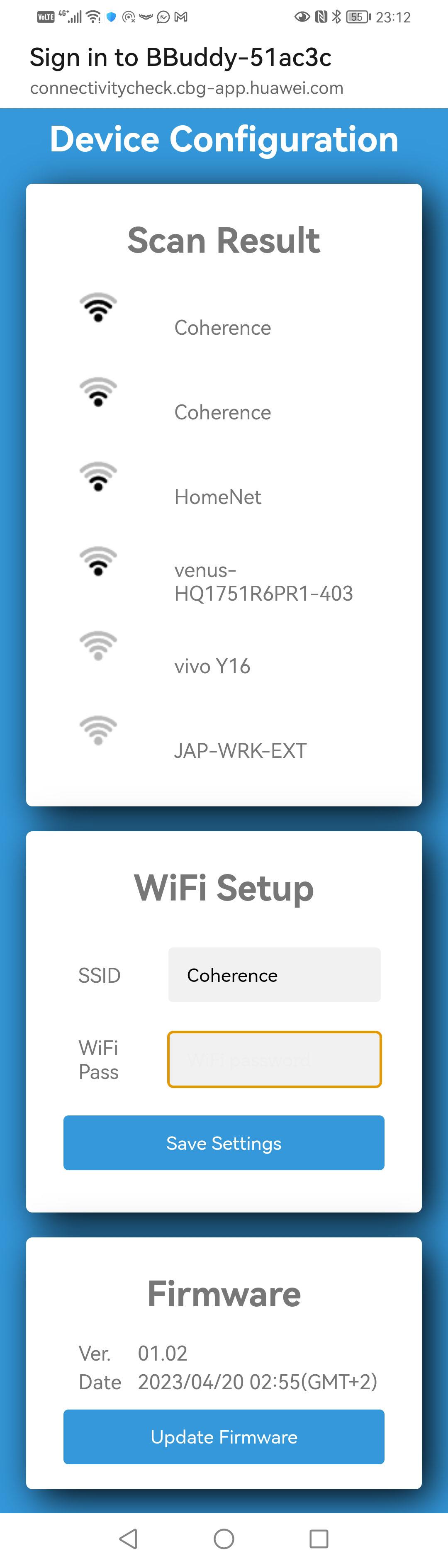
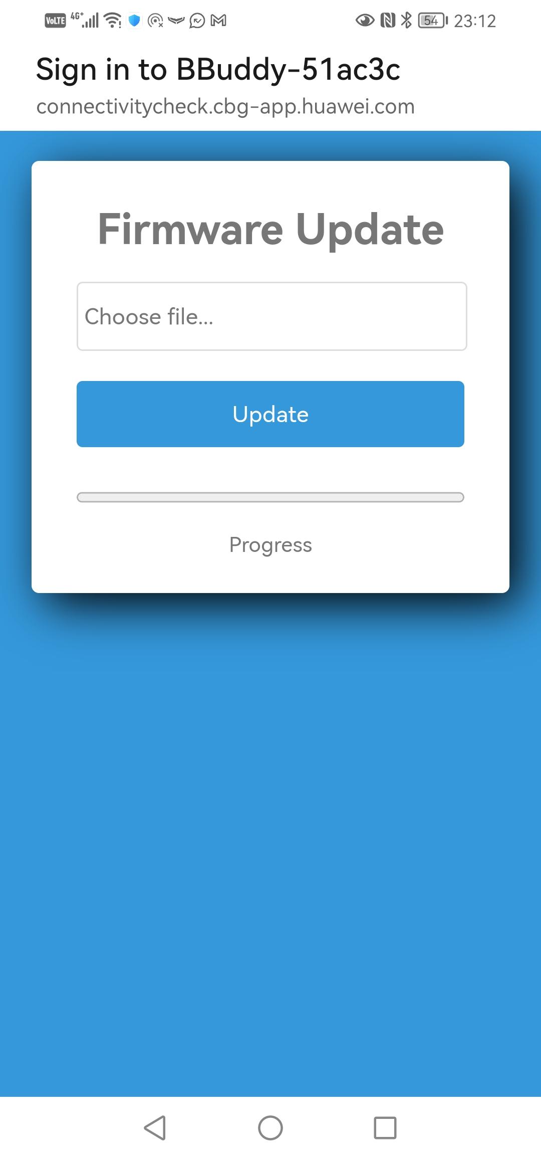
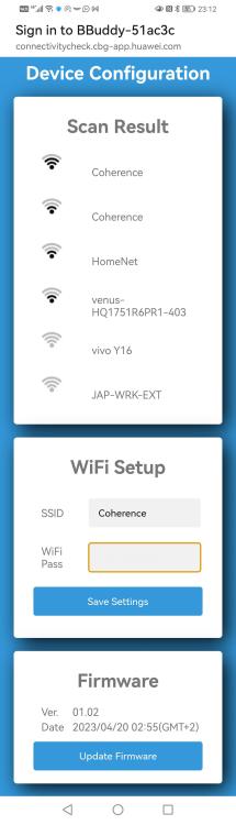
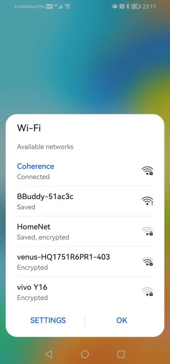
Good day all. I would like to share with you all my ideas and current progress on my project to create a cost effective and solid solution for battery monitoring and more. I have been focusing mostly on core functionality and will be adding features as I progress. The main drive of the project is to be able to monitor batteries that have CAN or RS485 or monitor batteries via inverters that have RS485. Other than providing metrics to the end user by tracking total energy in and out of the battery during charge and discharge cycles we could add functionality to activate "dry contact" relays on the unit to perform actions in the real world when conditions are met. eg at a certain DoD disconnect a load or add a beeper to be able to play a tone. I am currently querying batteries with canbus and have successfully tested with Hubble,Pylontech,LBSA and SRNE batteries. The core of the project is an ESP32 module that is WiFi enabled. You connect it to your network and from there you can access it using its multicast DNS name of buddy.local or its IP if you know how to obtain it or set a static DHCP lease for it. See attached files for screenshots of the setup user interface as viewed from a phone. Once the unit is online it also connects to "the cloud" and uploads its data. To see what I currently have you can visit http://bb.coherence.co.za/ and login with username demo and password demo. This should display 3 units. Only one is active really, and plugged into a battery emulator (more on that later). This is the "cloud" portion of the system and it will be capable of scaling to handle at least a million units but probably way more. This will probably never be necessary but I don't want to be painted into a corner from the get go. The data you see is streamed directly from the microcontroller to the cloud in realtime and various mechanisms are in place to ensure this only happens if people are trying to view the real time gauges. I am basically reaching out to the community to gauge interest, to see if anyone would be interested by providing feedback or assistance in any way they choose. I would be interested to see what kind of use cases / wish lists people can come up with, and help with testing is always invaluable, it is also my hope to leverage the excellent individuals that would be willing to help with their existing knowledge of protocols so that we don't have to re-invent the wheel. I look forward to hearing from you all.

-
To preface, I am not an electrician and I am not an expert. With that out the way... Don't confuse grounding (for lightning protection) and neutral bonding. Roughly speaking neutral bonding is the act of joining your neutral wire and earth, this is often done for safety and so that earth leakage detection devices function correctly. It is an important consideration when alternate supplies are installed (inverter generators etc) especially if they are not galvanically isolated inverters. Grounding on the other hand is the act of running a wire from an exposed metal chassis to ground so that the wire is the preferred electrical path and not your body(or anything else). To answer your question, no in my opinion you will not die . However if your grounding system develops a fault it is possible that a strike runs through your house to find the shortest path to ground. This is highly unlikely but I personally would have a local ground spike for the panels and additionally connect that to the house earth spike. An earth spike is cheap enough, hardest thing to acquire is the elbow grease to drive it into the ground. Side note, the earthing of solar panels is not only for lightning protection but mainly for protection from faults. Consider reading it contains a lot of useful information on the subject.
-
CAN is industry standard and yes there are various pinouts as there is no standard for the physical port. You should however find a way to get the battery talking to the Cerbo/Venus without much hassle. I found this https://www.sunsynk.org/_files/ugd/9350f7_c69a8ed8624d41c69e35e42ca0bc2ccf.pdf here https://www.sunsynk.org/532kwh-battery Which is for a UZ BMS which I assume is what they are using. Based on this the following cable should work. Even if this is not the exact sunsynk battery that you have I cant imagine they would vary their pinout between models. Sunsynk Pin 1 ----- CANH ------ Victron Pin 7 Sunsynk Pin 5 ----- CANL ------ Victron Pin 8 Sunsynk Pin 8 ----- GND ------ Victron Pin 3 The canbus speed is listed as 500K which is what I see on other batteries (hubble pylon LBSA) and the docs seem to indicate that the CANBUS is' are the same as those batteries too. You probably will not be able to use DVCC but definitely the inverter should see the battery. PS: by default the Victron GX seems to use a 250K data rate so just make sure that that's set correctly.
-
Thanks a ton, this was very informative. I doubt I will be able to convince my electrician(s) of it though. Both that consulted on my installation were insisting on a physically split DB. I don't mean to cause trouble and I know they must at times have a frustrating job dealing with amateurs, but I also do not want to slap a DB on a wall that I don't have to. Cost aside, its unsightly and based on their plan of action would require the extension of cables for any circuit that you want protected from the existing DB into the new one. This in itself introduces points of failure, mess and confusion. I see that there is a requirement in the code for a visual(or audible) indicator of the secondary feed status, which I had read in section 7.12 of the SANS code before, but which I have NEVER seen in practice in any DB that I have looked at. Could you clarify if the indicator is on the input or the output of the secondary feed isolator? In other words if I open the isolator in the DB should the pilot light turn off or stay on? In some respects it makes sense to me that it stays on, but in that case it seems to me that it would potentially be setting a precedent of also needing an indicator on the incoming grid feed too, as the light could lead to mixed messaging and incorrect assumptions. Many thanks again.